Write down the air condition the installed spray gun must receive, using its current manual, coating, operating mode, and specified connection point. Check that condition at the treated header and again at the gun during production. The comparison places the work: contamination already present before the header calls for central treatment, while a clean header followed by a poor endpoint points to the final branch or a documented gun-side requirement.
Some paint lines need both locations because each removes a different load. Others meet the gun requirement with one treatment layer. Assign every separator, dryer, filter, or regulator a named contaminant or control job, then include its pressure loss and service needs in the decision. A housing without a distinct job adds restriction and maintenance without proving that the required air reaches the spray gun.
Start with the air quality the spray gun must receive
The spray endpoint sets the target. Check the current manual for the gun, along with the coating and operating mode in use. Record what the equipment must receive and where that condition applies. A pressure, contaminant limit, or filtration instruction borrowed from another gun can send the treatment plan in the wrong direction.
Next, find out what the existing system delivers at that same location during production. Repairs, new branches, hose changes, and additional air users can alter endpoint conditions even when the central equipment has not changed. Paint Booth’s compressed-air drying and filtration basics explain the larger path between compressor and spray area.
ISO 8573-1 describes compressed-air purity classes for particles, water, and oil at the location where air is specified or measured. It describes the air, not the collection of hardware installed upstream. A dryer and three familiar filters don’t prove a class by their names alone. When a class applies, the stated location and suitable measurement matter; when it doesn’t, use the terms in the applicable equipment instructions.
Now the placement question has a firm starting point: the condition required at the gun versus the condition actually reaching it.
Put shared contaminant loads on central treatment
Air leaving a compressor carries heat and moisture, and it may also carry particles or oil depending on the supply and surrounding conditions. As the air cools, condensed liquid can enter receivers and piping unless the system removes and drains it. Those are shared loads when they exist before the distribution header divides.
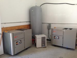
Central equipment handles that common work once rather than asking a small assembly at every paint bay to do it alone. An aftercooler and separator can remove condensed bulk liquid. A dryer addresses the moisture condition required farther downstream. Filters then perform different jobs: particulate elements capture solids, coalescing elements remove liquid aerosols, and adsorption media address vapors. The actual arrangement depends on the contaminant, dryer design, flow, inlet conditions, and current product instructions.
In a multi-bay shop, the central system must also support the periods when spray guns and other pneumatic tools operate together. A unit selected around average demand may see a very different flow during that overlap. Capacity and pressure loss must be checked at the operating condition that matters to production.
Central treatment gives every connected branch a controlled starting condition. It does not force every endpoint to use identical final treatment, nor does it confirm what arrives after a long distribution route. Paint Booth’s compressed-air system options show how the supply, treatment, and distribution pieces can be considered together.
Use point-of-use filtration for the final branch and gun
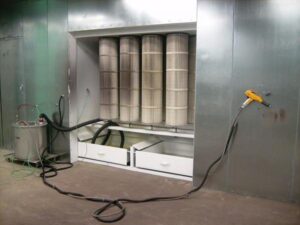
After central treatment, air still travels through pipe, valves, fittings, a regulator, couplers, and hose. An older branch can contribute corrosion particles. Liquid already present in a low point may remain in the route. A point-of-use stage can protect the gun from a condition that first appears along that final segment.
The local assembly may also provide the regulation or filtration named in the spray-gun instructions. Graco’s Stellair manual, for example, shows an air-line filter in its typical main-air-line installation and describes its job as removing dirt and moisture. That is a requirement for a named installation, not a universal filter rating or layout for every spray gun.
Hose length by itself doesn’t justify another filter. Compare air at the treated header with air near the gun under the same operating condition. If both points satisfy the endpoint requirement, another housing adds pressure loss and maintenance without a defined job. If the final route introduces a relevant contaminant or the gun requires tighter local control, point-of-use equipment has a clear purpose.
El compressed-air distribution route belongs in this comparison because local filtration can only address what reaches it. It cannot remove bulk liquid throughout the plant, protect other branches, or correct upstream moisture control.
Decide when the paint line needs both treatment layers
Three questions settle most placement disputes. Where does the contaminant first appear? Which branches share it? What must the spray gun receive at its connection?
| Layout | When it makes sense | What confirms the choice |
|---|---|---|
| Central treatment only | The load begins upstream, common equipment handles it at production flow, and the final route does not change the air beyond the gun’s requirement | Checks at the treated header and gun connection agree under the same operating condition |
| Central plus point-of-use | Common treatment removes the shared load, but the final branch introduces a separate risk or the gun calls for local control | The local stage has a named contaminant or endpoint job that central equipment cannot complete at that location |
| Point-of-use only | A limited dedicated branch receives air without a shared bulk-liquid, moisture, oil, or particle load that requires upstream treatment, and its endpoint has a distinct local need | The incoming condition and needs of the wider supply show that no common treatment job is being pushed onto the small local unit |
The third path is narrow. A point-of-use filter cannot stand in for bulk separation or drying required by the shared supply. When water or another contaminant exists before the branches divide, leaving it in the header affects more than the paint gun.
The combined layout earns its extra stage only when each layer performs a different job. Central equipment may handle condensed liquid and shared contamination; the gun-side assembly may handle debris introduced by the last branch or a local instruction from the equipment manufacturer. If both stages claim the same vague purpose, the design needs another look.
Count the pressure and service cost of every added stage
Every separator, dryer, filter, regulator, and connection creates resistance while air flows. The loss changes with component design, flow, and condition, so an idle gauge cannot show the cost during spraying. Read current manufacturer data for clean pressure drop, rated flow, inlet conditions, and the service indicator or limit used for that product. Then evaluate the full train at the shop’s actual demand.
Filter function matters here. Finer or additional treatment can cost pressure without helping the endpoint when the stage targets a contaminant that isn’t present. A coalescing element also needs protection from particulate loading according to its design; an adsorption element needs suitable upstream protection from liquid oil. Familiar-looking housings are not interchangeable.
Service work multiplies with local stages. Drains must discharge condensate as intended. Elements and indicators need access. Staff need to know which bay owns each service point and which current instruction governs it. A central assembly can concentrate some of that work, while a local filter at every gun spreads it across the shop.
Count those obligations before approving the layout:
- the job assigned to each stage and the contaminant state it addresses
- rated flow and pressure loss at the expected inlet condition
- drain, element, and protection requirements from the manufacturer
- safe access for inspection and service
- the pressure and air condition that must remain at the gun during production
If a proposed stage has no distinct job, it is another restriction to buy and maintain.
Specify the measurement point before choosing the equipment train
Give the supplier a route sketch instead of a filter count. Mark the compressor-room treatment, shared header, dedicated paint branch, regulator, couplers, hose, and gun connection. Identify the gun model and operating mode, the equipment running during checks, and the air condition found at the treated header and endpoint.
For every proposed stage, the supplier should be able to name its location, contaminant or control job, rated flow, expected pressure loss, drainage needs, and service access. The completed plan should also state where air will be checked against the gun requirement. That keeps an ISO class, when one applies, tied to air at a defined point rather than inferred from component labels.
A Paint Booth project quote can include the route, current equipment data, production demand, endpoint requirement, and observations. Those details let a qualified compressed-air provider select central and local equipment as one system.
Central treatment and point-of-use filtration are not competing versions of the same purchase. One controls what enters the shared distribution system; the other protects a specific endpoint after the air has crossed its final route. Give each stage a real job, check the result where the gun uses the air, and stop adding housings when the endpoint requirement has been met.