
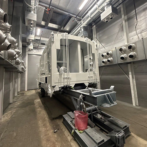
An existing paint booth cannot cure a UV coating simply because it can spray it. Spray booths manage airflow, particulate capture, and solvent or monomer exhaust; curing requires targeted electromagnetic radiation delivered at specific wavelengths, intensities, and angles of incidence.
Adopting ultraviolet (UV) chemistry in a facility running traditional solvent-borne, waterborne, or thermal-cure coatings is not a simple plug-and-play retrofit. The finishing manager must evaluate the coating chemistry, part profile, lamp specifications, and ventilation interlocks as separate engineering disciplines before assigning production parts to an existing cabin.
Defining the Material: Spot Repair Primer vs. Industrial Topcoat
UV-curable coatings vary widely in chemistry, solids content, and curing requirements. Grouping them into a single category creates costly assumptions on the shop floor.
| Product Consideration | Spot-Repair Primer | Industrial Production Coating |
|---|---|---|
| Formulation | Verify carrier and solids for the exact primer. | Verify carrier and solids for the exact coating. |
| Lamp equipment | Use the product-specified suitable lamp. | Verify the proposed production lamp arrangement. |
| Film build | Use the primer’s specified build. | Use the coating’s specified build and line conditions. |
| Coverage | Evaluate localized shadowing. | Evaluate all coated geometry and shadowing. |
A collision-repair primer surfacer designed for rapid spot prep has little in common with a 100% solids industrial UV clearcoat applied to continuous composite beams. For instance, the PPG SU1280 UV primer instructions illustrate a product engineered for localized body repairs. In that operational envelope, a technician coats a featheredged patch and exposes it to a calibrated handheld UV-A lamp. Its instructions specify compatible surfaces, film build, direct exposure and UV protection; its process does not establish a general industrial cure protocol.
Industrial topcoats and high-performance primers, by contrast, often carry aggressive photoinitiator packages tuned to specific bands—such as UVA, UVB, UVC, or UVV. These formulations frequently contain reactive diluents (such as monofunctional or polyfunctional acrylates) whose exposure and ventilation requirements depend on the exact product and process.
Before inspecting your spray booth, identify the exact coating category:
- Solvent-borne UV blends: Coatings that carry conventional volatile organic compounds (VOCs) to reduce viscosity for standard spray guns. Their instructions determine whether flash-off is required before cure.
- 100% reactive solids: Formulations containing zero solvent carriers, whose reactive ingredients are intended to form the cured film. Check the actual formulation, any required intermediate stages and sensitization hazards in its documents.
- Waterborne UV polyurethane dispersions (PUDs): Systems whose product instructions specify water-removal and irradiation requirements.
Ventilation, Capture, and Cross-Contamination Risks
A common misconception is that switching to UV coatings removes the need for industrial exhaust rates. UV-curable products still release atomized overspray, photoinitiator mists, and in many cases, standard carrier solvents.
Exhaust volume must remain high enough to maintain capture velocity across the entire spraying zone. Acrylate-containing mists can present skin, respiratory or sensitization hazards depending on the formulation; letting overspray linger in an under-ventilated enclosure puts operators at direct risk. In enclosed industrial paint booths, suitable airflow helps limit overspray drift from depositing on curing lamps or observation windows.
- Intake filtration and airflow
- Spray-zone overspray capture
- Proposed curing zone and shielding from atomization
- Exhaust collection and discharge arrangement
- Verify the relationship among these zones for the actual booth; this list is not a retrofit layout.
Facility managers must also evaluate material switching. If the booth sprays standard polyurethane, epoxy, or nitrocellulose lacquers on one shift and UV coatings on the next, filter residues can become a fire risk.
Under federal OSHA spray finishing requirements, specific operational rules restrict material alternation:
- Combustible Residue Interactions (29 CFR 1910.107(g)(6)): The provision requires removal of deposits before alternating specified materials whose combined deposits may promote spontaneous ignition.
- Filter Maintenance (29 CFR 1910.107(b)(5)(vi)): The provision restricts alternating use of filters for coating combinations conducive to spontaneous ignition; exact materials must be assessed rather than assuming UV polymers are incompatible.
- Drying and Curing Coordination (29 CFR 1910.107(j)): Review applicable drying safeguards, equipment approvals and interlocks; this provision does not authorize simultaneous spraying and UV curing based on ventilation alone.
Part Geometry, Shadowing, and Lamp Coverage
Thermal ovens bake coatings by elevating ambient air temperature, transferring heat into interior channels, blind holes, and reverse faces. Ultraviolet light does not work this way. Photons travel in straight lines; a UV-only process needs sufficient exposure at each coated surface; dual-cure formulations may provide an additional cure mechanism.
| Part Feature | UV Penetration Risk | Operational Consequence | Mitigation Strategy |
|---|---|---|---|
| Flat Panels / Sheets | Coverage still needs verification | Irradiance can vary across the surface | Verify the proposed lamp coverage and product requirements |
| I-Beams / Structural Channels | Possible shadowing | Flanges can shield inner webs | Evaluate orientation and approved lamp coverage |
| Blind Bores / Deep Recesses | Potentially limited exposure | Cure may be incomplete where exposure is insufficient | Verify suitability, including any specified dual-cure mechanism |
| Threaded Bosses / Brackets | Possible shielding | Undersides may receive insufficient direct exposure | Verify a supplier-approved exposure arrangement |
A booth configured for manual spray can physically fit three-dimensional weldments, but curing those weldments requires a fully engineered lamp envelope. If a technician uses an uncalibrated, handheld light source, adequate cure cannot be assumed across the part profile.
- Directly exposed faces: Verify delivered irradiance and dose.
- Shadowed pockets: Verify whether exposure is sufficient for the selected chemistry.
- Reflected-light areas: Measure or validate the actual exposure; do not assume a fixed fraction of lamp energy.
Variations in working distance alter energy density. The distance–irradiance relationship depends on the source geometry and optics; use the lamp manufacturer’s specified working range rather than a generic inverse-square calculation. Uncured, hidden runs or shadowed seams leave wet monomer on finished goods, which can compromise performance and expose handlers to uncured material.
Safety Controls, Interlocks, and Electrical Classifications
Integrating UV-curing arrays directly inside or adjacent to an existing booth envelope triggers strict mechanical and electrical zoning requirements.
High-output arc lamps (mercury vapor, metal halide) and modern UV-LED banks draw substantial electrical loads. If curing equipment is positioned inside the spray booth cabin, its suitability must be checked against the actual electrical area classification and applicable requirements.
Arc lamps can introduce heat and ignition hazards; the proposed operating arrangement requires equipment and hazard review rather than a generic lamp-type assumption.
- Purge and Interlock Cycles: Have the equipment manufacturer and responsible engineer define the required spray, cure, ventilation and purge safeguards for the actual arrangement; do not improvise an interlock sequence.
- Optical Shielding: UV exposure can injure eyes and skin. Select shielding, observation windows and personal protection for the actual source spectrum and exposure, following the lamp and coating instructions; ordinary glazing is not proof of suitable protection.
- Ozone Mitigation: Some UV sources generate ozone. Check the lamp’s documented emissions and have ventilation and exposure controls assessed for the actual source; do not infer a safe atmosphere or return-air permission from lamp type.
Facilities planning larger line modifications frequently rely on engineered finishing systems that isolate the application zone from the curing chamber using automated air locks or vestibules, as part of controlling overspray and lamp hazards.
Pre-Adoption Compatibility Packet
Finishing managers should avoid making assumptions based on supplier marketing claims of "instant cures." Before purchasing lamps or chemistry, compile a documented engineering packet to assess your current booth's viability.
- Coating TDS and SDS: Formulation, specified spectral requirements, irradiance, dose and film build.
- Lamp specifications: Spectrum, working distance, coverage, electrical suitability and cooling requirements.
- Part and carrier profiles: Coated faces, blind zones, orientation and movement.
- Booth records: Documented airflow, exhaust capacity, control schematics and media compatibility.
Once this packet is compiled, work directly with coating formulators and booth engineers to run line trials. Use the coating supplier’s specified cure-verification methods and acceptance criteria across representative faces and recessed areas; solvent rubs, adhesion or hardness alone do not directly establish cure depth.
If you are evaluating whether to modify an existing spray cabin, install dedicated curing arrays, or expand production with automated lines, request a finishing equipment quote to review your process parameters with an engineer.