
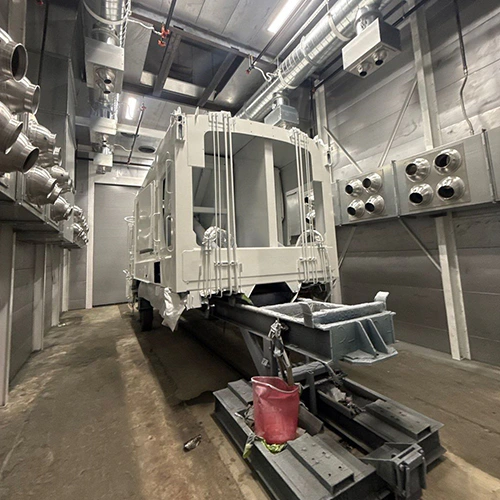
Standard blast cabinets and off-the-shelf blast rooms may not satisfy the operational demands of high-throughput manufacturing, heavy fabrication, or specialized coating facilities. When parts exceed standard dimensions, require aggressive profile depths, or demand continuous shifts, standard designs create severe bottlenecks.
A custom blast booth aligns the physical structure, recovery floor, handling gear, and air filtration with your specific production cycle. Designing one requires looking past surface-level footprints and treating the installation as an integrated chemical, mechanical, and material handling process.
Define Part, Surface-Preparation, and Throughput Needs
Your part envelope and surface profile target guide the enclosure dimensions and equipment requirements in the room. A custom installation must balance physical clearances against the energy required to clean and recirculate your abrasive.
- 1. PART METRICS
- Max Length x Width x Height
- Total Mass
- Tare/Rigging
- 2. SURFACE TARGETS
- Anchor Profile (mils)
- Cleanliness Spec (SP 5 / SP 10)
- 3. MEDIA SELECTION
- Ferrous (Steel Shot/Grit)
- Non-Ferrous (Garnet, AlOx, Glass)
- 4. PRODUCTION CADENCE
- Nozzle Run Time/Shift
- Operator Count
- Target Cycle Time
Workpiece Envelope and Load Weight
Begin with a detailed inventory of the parts you intend to blast:
- Maximum Dimensions: Record the true maximum length, width, and height of your largest fabricated assembly, including any handling fixtures or shipping skids.
- Mass and Point Loads: Quantify both the overall workpiece weight and the concentrated point loads exerted on the floor by wheel sets, cart casters, or dunnage.
- Geometry and Shadow Zones: Complex weldments, internal pipe surfaces, and structural trusses require multi-angle blasting. This demands operator clearance and adjustable staging rather than simple overhead illumination.
Surface Specification and Media Match
The blast profile depth (measured in mils) and target surface cleanliness (such as SSPC-SP 10 / NACE No. 2 Near-White or SSPC-SP 5 / NACE No. 1 White Metal) dictate your choice of abrasive.
When evaluating industrial sandblasting booth options, remember that the chosen media dictates your reclamation equipment:
- Steel Shot and Grit: High-density, high-durability media ideal for heavy rust, mill scale removal, and aggressive anchor profiling on structural carbon steel. Steel media can support repeated reuse, with recovery capacity selected for its properties and your production demand.
- Aluminum Oxide and Silicon Carbide: Aggressive, non-ferrous abrasives used on aerospace alloys, stainless steel, or composites where iron cross-contamination is prohibited. These cut fast but break down into fine dust more rapidly than steel.
- Garnet: A naturally occurring mineral abrasive frequently specified for marine and industrial maintenance. It bridges the gap between aggressive profiling and lower friability, performing well in pneumatic or light mechanical reclaimers.
- Glass Bead and Plastic Media: Delicate media used for light deburring, peening, or stripping sensitive substrates where limited substrate removal is required. Their wear and breakdown depend on the process; a compatible separator must distinguish reusable media from fines.
Throughput and Duty Cycle
Determine your blast trigger time: the actual hours per shift that blast nozzles will discharge media.
Lower-volume work may accommodate manual broom-in recovery, while higher duty cycles may justify automated recovery. Dust control must meet the process requirements at either production level.
Match Enclosure and Handling Access to the Work
Handling logistics determine the room's footprint, door architecture, and floor engineering. If an operator cannot safely negotiate a 50-foot blast hose around a loaded part, handling and cycle time will suffer.
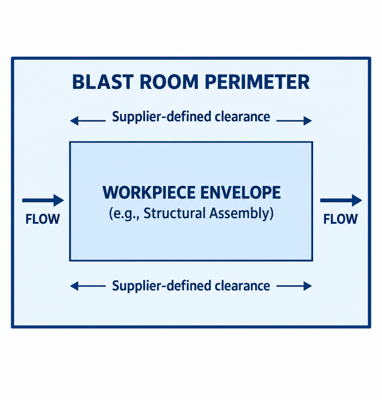
Diagram description
- BLAST ROOM PERIMETER
- Supplier-defined clearance
- WORKPIECE ENVELOPE
- (e.g., Structural Assembly)
- FLOW
- BLAST ROOM PERIMETER → WORKPIECE ENVELOPE: contains; clearance above and below
- FLOW → WORKPIECE ENVELOPE: rightward inflow
- WORKPIECE ENVELOPE → FLOW: rightward outflow
- BLAST ROOM PERIMETER
- WORKPIECE ENVELOPE
- Supplier-defined clearance
- FLOW
- WORKPIECE ENVELOPE
- (e.g., Structural Assembly)
- BLAST ROOM PERIMETER outer container encloses WORKPIECE ENVELOPE with qualifier (e.g., Structural Assembly).
- Two horizontal double-headed dimension lines above and below inner envelope each labelled Supplier-defined clearance.
- FLOW arrows on left and right both point right, into and out of workpiece respectively.
Perimeter Clearances and Working Envelopes
A blast room needs working clearances established for the part, handling equipment, operator access, and egress. This clearance accommodates:
- Operator mobility while wearing blast suits, helmets, and heavy personal protective equipment.
- Natural blast hose sweep angles without sharp hose kinks.
- Safe egress paths that remain unobstructed if a workpiece shifts during processing.
For a preliminary envelope check, use supplier-defined clearances in the following relationships, then validate the complete handling layout:
Internal Length = Maximum Part Length + 2 × (Required Perimeter Clearance)
Internal Width = Maximum Part Width + 2 × (Required Perimeter Clearance)
Internal Height = Maximum Part Height + Material Handling Clearance
Workpiece Transfer and Door Configurations
Work handling dictates your wall and roof openings:
| Transfer Method | Typical Application | Enclosure Consideration |
|---|---|---|
| Overhead Bridge Crane | Heavy structural fabrications, weldments, castings | Requires a roof crane slot with motorized or brush-type blast seals to prevent media escape while the hoist rope runs. |
| Work Car / Rail Transfer | Predictable, symmetrical parts on dedicated shop carts | Embedded floor rails with custom cross-travel recovery floor seals; optional internal work car turntables for 360-degree part rotation. |
| Forklift Access | Palletized parts, modular assemblies | Heavy-duty drive-over floor grating; reinforced door thresholds; push-in/pull-out operational staging. |
| Monorail Conveyor | Continuous-flow manufacturing, pipe, line-fed parts | Cantilevered pass-through vestibules with multi-layer hanging rubber baffles at ingress and egress points. |
Door configurations reflect these material paths. Large single-end or drive-through bi-fold, swing, or vertical-roll fabric doors accommodate moving parts in and out. Fast-acting motorized roll-up doors preserve interior plant space, whereas swing doors provide lower mechanical complexity at the cost of clear floor radius outside the room.
Enclosure Protection and Structural Ventilation
Bare structural steel walls deteriorate rapidly under secondary media ricochet. High-durometer, hanging vulcanized rubber or white abrasion-resistant curtains absorb ricochet energy, deaden sound, and brighten the blast environment to improve operator sight lines.
Because physical work positioning determines the intake and exhaust air pathways, duct transitions linking the room to exterior dust collection systems must be coordinated early to prevent dead zones where airborne particulate settles instead of venting.
Intake air louvers should be placed across the entry doors or ceiling plenums, supporting a designed airflow path that pulls suspended dust away from the operator's visor toward low-level or end-wall exhaust plenums.
Coordinate Media Recovery and Dust-Control Interfaces
The physical characteristics of your media dictate how the recovery floor must be engineered. Abrasive recovery systems include pneumatic and mechanical designs. Matching the wrong recovery system to high-density media creates severe maintenance downtime and plugged conduits.
RECOVERY TYPES
- PNEUMATIC RECOVERY
- Airflow vacuum lift
- Light media: Garnet, AlOx
- Compare lifecycle cost
- Pitless / shallow depths
- MECHANICAL RECOVERY
- Augers, screws, bucket lifts
- Heavy media: Steel shot/grit
- High throughput & volume
- Pit or above-ground options
Mechanical vs. Pneumatic Recovery
- Mechanical Recovery (Augers, Belt/Bucket Elevators, Oscillating Pans): Heavy media like steel shot and steel grit (with high bulk density) often suit mechanical recovery. Heavy-duty screw conveyors or vibratory pans collect fallen media and convey it to a vertical belt-and-bucket elevator, which lifts it into an air-wash separator. Compare recovery capacity and energy demand for the selected media and actual layout.
- Pneumatic Recovery (High-Velocity Vacuum Extraction): Suitable for lower-density mineral and agricultural media (glass bead, aluminum oxide, walnut shells) or light-duty maintenance operations. Vacuum recovery utilizes high-velocity air streams to pull abrasive along collection floor troughs. While mechanical complexity inside the booth floor is minimal, vacuum systems lose efficiency quickly over long horizontal runs and demand high horsepower when handling dense ferrous media.
Floor Configuration Architecture
The depth you can cut into your facility's concrete foundation determines whether your reclaim floor sits in an excavated pit or requires an above-ground ramp.
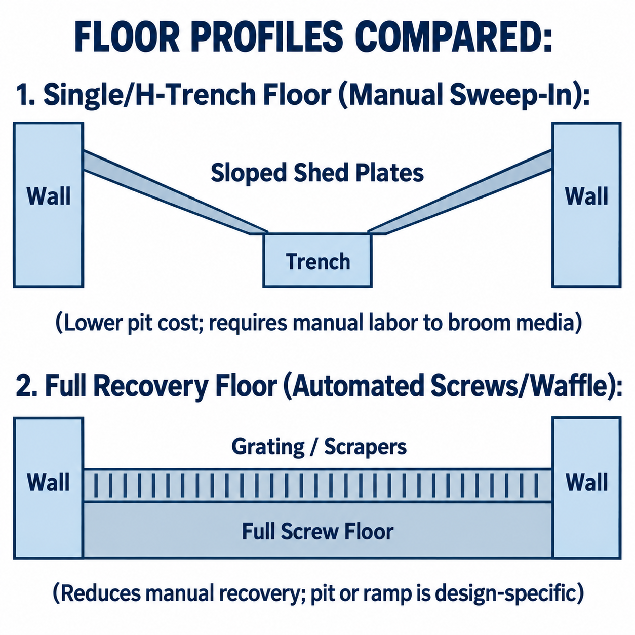
Diagram description
- FLOOR PROFILES COMPARED:
- 1. Single/H-Trench Floor (Manual Sweep-In):
- Wall
- Sloped Shed Plates
- Trench
- Wall
- (Lower pit cost; requires manual labor to broom media)
- 2. Full Recovery Floor (Automated Screws/Waffle):
- Wall
- Grating / Scrapers
- Full Screw Floor
- Wall
- (Reduces manual recovery; pit or ramp is design-specific)
- Upper comparison: two wall rectangles flank two downward inward sloping shed plate lines meeting a center trench at bottom.
- Lower comparison: two wall rectangles flank horizontal grating / scrapers above full screw floor.
- Each parenthetical qualifier is below its own profile; no arrows or invented hardware.
- Single-Screw or H-Shaped Center Trench: Media falls onto concrete or steel shedding plates. Blasters broom or shovel fallen abrasive into a central recessed trench at intervals. This can reduce floor construction work, but adds manual recovery labor.
- Full-Floor Screw Recovery: The entire floor surface consists of open bar grating over longitudinal screw conveyors feeding a transverse cross-screw. Media recovery can reduce sweeping labor. Pit depth or above-ground access requirements come from the selected design and foundation drawings.
- Waffle-Style Pneumatic Floor: Employs narrow, shallow-depth channels (depth specified by the manufacturer) with swinging flap-valves. It offers full-floor automated reclaim without deep excavation, with media compatibility and airflow requirements determined by the selected model.
Media Cleaning and Sizing Separation
Reclaimed media must be classified before feeding back into the blast pot. Reusing unclassified abrasive leads to rapid nozzle wear, irregular surface profiling, and dust clouding:
- Rotary Scalping Drums: Catch coarse weld slag, wire pieces, paint chips, and debris that fall through floor gratings, protecting downstream nozzles from plugging.
- Cascading Air-Wash Separators: Drop falling abrasive sheets through a precision horizontal air curtain. Reusable media is retained, while rejected-material routing depends on the separator design. In the Clemco AWAC example, fines discharge through a fines chute and dust travels to the dust collector.
- Magnetic Drums: An option when ferrous contamination must be separated from a non-ferrous abrasive; suitability depends on the contaminants and reclaim design.
Airflow Velocity and Ventilation Rates
Ventilation controls operator visibility and dust clearance. Airflow must maintain velocity without prematurely pulling reusable abrasive out of the room:
- Crossdraft Rooms: Air enters the ceiling or entry doors at one end and exhausts through the opposing wall. The supplier establishes the airflow requirement for the enclosure, media, and dust load.
- Downdraft Rooms: Air enters through ceiling distribution plenums and sweeps vertically straight down through the floor grating. Suitability for the work and any toxic coating removal requires a process-specific ventilation and exposure-control review.
For a specified uniform design velocity, airflow is related to face area by the following equation; it does not select the required velocity or replace supplier ventilation design:
Required Ventilation CFM = Airflow Face Area (sq. ft.) × Design Velocity (FPM)
Prepare a Supplier Review Brief
Suppliers cannot size mechanical elevators, filtration fans, or drive components without exact operational criteria. Broad or incomplete inquiries yield generic estimates that require costly revisions during design review.
When you request a blast booth quote, provide these physical parameters as a structured scope document rather than asking vendors to guess your workflow.
Facility and Site Data Checklist
Before engaging equipment builders, compile the physical constraints of your facility:
- Clear Height Under Hook: Measure clear ceiling space, taking into account overhead building steel, lighting, gas lines, and existing crane runways.
- Concrete Foundation Data: Check current slab thickness, rebar reinforcement, soil condition, and groundwater tables (which dictate whether a deep reclaim pit is feasible without expensive waterproofing).
- Compressed Air Supply: Quantify available volume in standard cubic feet per minute (CFM) at the specified operating pressure, air dryer capability (dew point specs), and dedicated receiver storage size. The selected nozzle sizes, pressures, and simultaneous operator count determine air demand.
- Electrical Service: State available line voltage, phase, and available total panel amperage dedicated to the blast building, mechanical drives, and collector blowers.
The Application Scope Template
Package your processing requirements into a clear, single-page matrix:
CUSTOM BLAST ENCLOSURE SPECIFICATION BRIEF
- Workpiece Dimensions:
- Maximum Envelope: _____ L x _____ W x _____ H (ft/in)
- Maximum Gross Load Weight: _____ lbs
- Handling Method: [ ] Overhead Crane [ ] Rail Car [ ] Forklift [ ] Other: _____
- Substrate & Surface Cleanliness Criteria:
- Base Metal / Metallurgy: _________________________
- Initial Surface Condition: [ ] Mill Scale [ ] Rust Grade [A/B/C/D] [ ] Heavy Coating
- Cleanliness Target: [ ] SSPC-SP 5 [ ] SSPC-SP 10 [ ] SSPC-SP 6 [ ] Other: _____
- Target Surface Profile: _____ mils
- Abrasive Media Selection:
- Media Type & Mesh/Grit Size: _________________________
- Media Bulk Density: _____ lbs/cu. ft.
- Floor Type Desired: [ ] Full Screw Auto-Reclaim [ ] Single-Trench Sweep-In [ ] Waffle Floor
- Duty Cycle & Staffing:
- Blasting Shifts per Day: _____ | Operating Days per Week: _____
- Simultaneous Blast Operators: _____ (Nozzle Size: #[____])
- Target Trigger-Time per Shift: _____ hours
- Facility Constraints:
- Pit Depth Allowance: [ ] Pitless Only [ ] Max Pit Depth: _____ inches
- Overhead Clearance Restrictions: _____ ft
- Dust Collector Location: [ ] Indoor Adjacent [ ] Outdoor Pad (Distance: _____ ft)
Use this brief to anchor your vendor walk-throughs. By defining your part metrics, material handling approach, and abrasive reclamation physics up front, you force equipment suppliers to compete on real engineering specs rather than ambiguous base models.