
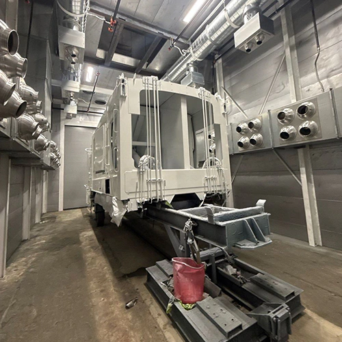
Air filtration systems fail when equipment engineered for dry particulate is forced to handle liquid droplets, or when mist units are choked with dry grinding grit. While both systems pull contaminated air through a housing to protect workers and maintain indoor air quality, their media, cleaning, drainage, and material-compatibility requirements can differ substantially.
Treating dust and mist collectors as interchangeable creates severe operating problems: rapidly blinded filters, puddles of coolant inside ductwork, ruined blowers, and acute fire hazards. Specifying the correct technology requires looking past nominal airflow ratings and analyzing the physical state of the contaminant at the point of generation.
Classifying Airborne Contaminants: Solids, Aerosols, and Vapors
Industrial processes generate three distinct categories of airborne emissions. Identifying which one leaves your machine tool, blast cabinet, or spray area determines the separation mechanics your system requires.
| Contaminant phase | Selection question |
|---|---|
| Dry solid | What particle properties, loading, and hazards must the system handle? |
| Liquid aerosol | What fluid, droplet distribution, mixed solids, and drainage must it handle? |
| Gas-phase vapor | What ventilation or gas-treatment controls are required beyond mechanical particulate collection? |
Dry Solids (Particulate Dust)
Dry particulate consists of discrete solid particles generated through mechanical abrasion, cutting, impact, or thermal degradation. Common examples include wood sanding dust, metal grinding debris, shot blast fines, and powder coating overspray.
These particles range from sub-micron fume up to macroscopic chips. Their behavior depends on particle size, cohesion, and process conditions; compatible collectors may capture them on media and use an appropriate cleaning method.
Liquid Aerosols (Mist and Smoke)
Mist consists of liquid droplets suspended in an airstream, typically generated by liquid atomization, high-pressure fluid delivery, or mechanical shearing. Droplet size varies widely with the fluid and generation process.
When high-temperature processes vaporize oil or coolant, the vapor cools and condenses into ultra-fine droplets (often under 1 micron), appearing as oil smoke. Because these contaminants are true liquids, they wet whatever surface they contact, cling via surface tension, and can saturate incompatible dry media and sharply restrict airflow.
Gas-Phase Vapors
Vapors are volatile substances in a gaseous state. Evaporating paint thinners, solvent degreasers, and the volatile organic compounds (VOCs) emitted during resin curing are vapors, not aerosols.
Mechanical filtration cannot capture gas-phase vapors. A mist collector can separate suspended droplets of mineral oil, but it will not remove the evaporated solvent vapors circulating in that same airstream. Capturing vapors requires activated carbon adsorption, thermal oxidation, or dedicated facility exhaust systems.
Separation Mechanics: Filtration Cake vs. Coalescence
Dry and liquid collection can share interception and impaction mechanisms, while their media handling and discharge requirements differ.
- Many media dust collectors capture particles on filter surfaces and use specified cleaning to discharge collected solids.
- Many fibrous mist collectors combine droplet coalescence with specified drainage and media maintenance.
- These are common arrangements, not universal definitions of every collection technology.
How Dry Dust Collectors Operate
Many industrial dust collectors, including cartridge and baghouse designs, rely on media filtration; other dust-collection technologies also exist. As dirty air passes through pleated cartridges or woven bags, particulate deposits on the outer surface of the media.
Over time, this accumulated dust forms a "filter cake." Counterintuitively, this cake layer actually increases filtration efficiency by trapping smaller incoming particles before they reach the substrate pores.
To maintain continuous operation, cartridge dust collectors fire short, high-pressure pulses of compressed air down the center of each cartridge. This pulse briefly expands the media and knocks the accumulated dust cake off the exterior surface, allowing it to drop by gravity into a collection hopper or drum below.
How Mist Collectors Operate
Liquid mist cannot form a dust cake. When droplets strike dry filter media, they soak into the fibers, fill the interstitial voids, and block airflow.
Many fibrous mist collectors use coalescence and drainage; centrifugal and electrostatic designs use other arrangements. In a coalescing design:
- Impaction: Liquid-laden air enters the collector and passes through progressively dense fibrous beds or metal mesh stages.
- Coalescence: Tiny aerosol droplets strike the media fibers, hold position through surface tension, and collide with incoming droplets to form progressively larger beads of fluid.
- Gravity Drainage: Once a droplet grows large enough, its mass overcomes aerodynamic drag and surface tension. The liquid drains downward through the media under gravity, completely independent of compressed-air pulses.
- Sump Evacuation: The coalesced fluid channels down internal baffles and drains through a trapped drain port into a collection container or directly back into the machine tool sump.
The Consequences of Technology Cross-Contamination
Feeding wet coolant mist into a dry cartridge dust collector can cause media blinding or "mudding" when the collector and media are unsuitable for the mixed load. The liquid combines with ambient dust to form a dense paste over the pleated cartridges. Pulse cleaning may not restore unsuitable, liquid-blinded media. Resistance can rise and delivered airflow can fall; this is not motor cavitation.
Conversely, feeding high-solids dry particulate into a standard mist collector converts the coalescence stages into a sludge trap. Heavy particulate settles in the drain troughs, blocks the liquid P-traps, and forces collected oils or coolants to back up inside the housing, eventually pulling dirty liquid through the blower wheel.
| Feature / Dynamic | Dry Dust Collector | Mist Collector |
|---|---|---|
| Primary Media Role | Compatible particulate capture; cake filtration in many media units | Droplet separation by the selected technology |
| Cleaning Mechanism | Reverse compressed-air pulse, vibration, or manual replacement | Drainage and manufacturer-specified media maintenance |
| Discharge Phase | Dry bulk solid (hoppers, drums, rotary airlocks) | Continuous liquid stream (P-trap, drain pan, return hose) |
| Duct Design Requirement | Material-specific transport and protection requirements | System-specific liquid-tightness and drainage requirements |
| Failure Mode Under Mixed Load | Media "mudding," permanent blinding, hopper compaction | Sump sludging, drain clogs, media wash-through |
Mixed Loads, Coolant Mists, and Fire Hazards
Few industrial operations generate perfectly clean, single-phase contaminants. Metal cutting, wet grinding, and heavy machining throw both liquid coolant aerosols and metallic fines into the exhaust hood simultaneously.
| Process | Compatibility concern |
|---|---|
| Machining coolant with fines | Match fluid chemistry and mixed particulate loading; assess fire hazards |
| Coating overspray | Use approved finishing collection equipment; machining-mist suitability does not establish paint compatibility |
Machining centers use neat cutting oils, semi-synthetics, or water-soluble fluids, each behaving differently inside an air cleaner. Fluid type, droplet size, temperature, and particulate loading determine the compatible media stages and any required downstream filtration; neither fluid label dictates a universal HEPA or media arrangement.
Engineering references such as Donaldson’s Dryflo application guidance emphasize matching internal media configurations directly to the specific fluid chemistry—whether oil, water-soluble, or synthetic coolant machining mist. That guidance illustrates how internal stages must be arranged differently when particulate loading changes relative to liquid volume, while maintaining strict warnings regarding fire and explosion risks in metalworking environments. Crucially, equipment built to those specifications does not authorize paint solvent/mist service.
Finishing operations introduce an entirely different chemical and physical hazard profile. Liquid paint overspray is not an industrial coolant; it contains atomized resins, polymers, and volatile organic carriers that dry through solvent evaporation or chemical curing.
Where machining mists drain passively through coalescing media, coating particles stick permanently on contact. This is precisely why finishing enclosures rely on a dedicated paint arrestor filter function. Paint arrestor media captures tacky overspray before it coats the exhaust fan or builds up in discharge stacks, using the approved arrestor structure and retention method rather than assuming every medium has progressive-density stages.
Fire risks escalate dramatically across both domains:
- Combustible Dusts: Fine aluminum, magnesium, titanium, and organic dusts form explosive clouds inside dry collectors if an ignition source is introduced. A process-specific combustible-dust assessment determines required prevention, protection, and isolation measures; venting and suppression are not universally required together.
- Flammable Mists and Resins: High-pressure atomization of low-flashpoint cutting oils or solvent-borne coatings creates an explosive vapor/aerosol mixture. Standard pulse-jet valves, ungrounded filter cages, or non-rated blower motors can provide an immediate ignition path.
Evaluating the Complete Collection System
Specifying an air filtration system based solely on a catalog CFM (cubic feet per minute) rating often leads to undersized, high-maintenance installations. A complete system consists of several integrated subsystems:
- Assess source capture and enclosure geometry.
- Match duct transport, material compatibility, and drainage to the process.
- Specify compatible collector media and required hazard controls.
- Verify solids discharge or liquid drainage and maintenance access.
- Select fan and discharge arrangements for the documented system resistance and applicable requirements.
Source Capture and Hood Geometry
The collection process starts at the machine enclosure or workstation. Hoods must be placed as close to the point of generation as possible, using the momentum of the thrown particulate or aerosol to direct it into the capture zone.
For mist capture on enclosed CNC machines, hoods must maintain a slight negative enclosure pressure without pulling heavy fluid sheets off the cutting tool. For dry dust, hood entry velocities must overcome ambient cross-drafts without sucking up raw, unworked material stock.
Ductwork Configuration
A duct system designed for dry dust will leak liquid onto the shop floor if repurposed for mist:
- Dry Dust Ducting: Requires transport conditions selected for the actual material and system to keep particles suspended in the airstream until they reach the collector hopper. If velocities drop, dust falls out of the air and settles inside the duct runs, creating structural weight loads and fire paths.
- Mist Ducting: Requires velocity, liquid-tightness, slope, and drainage specified for the actual mist system; do not derive a universal velocity or drain direction from the equipment label.
Waste Evacuation and Maintenance Access
A collector is only as functional as its discharge mechanism. Dry dust collectors demand discharge geometry compatible with the dust’s flow properties and collector design feeding into sealed drums, slide gates, or rotary airlocks. Opening an active dust collector hopper without an isolation valve destroys draft pressure and spills dust back into the facility.
Where the installed negative-pressure mist collector specifies a trapped drain, use its documented trap and drain arrangement. Because the collector operates under negative pressure induced by the fan, an open drain port will simply suck air inward, trapping the liquid inside the housing and flooding the lower filter stages. The drain trap must provide enough liquid head height to break the negative static pressure developed by the exhaust fan.
Technical Information Required for an Equipment Inquiry
Before contacting manufacturers or system designers, compile the operational parameters of your process. Providing complete upstream data prevents misapplication and avoids costly retrofit work.
Contaminant Profile Checklist
Gather the following data directly from the plant floor:
- Source Generation: Identify the exact physical process (e.g., centerless wet grinding, dry abrasive blasting, automated spray application, multi-axis milling).
- Material Safety Data Sheets (SDS): Review the chemical compositions of all fluids and substrates. Note whether cutting fluids are neat mineral oils, semi-synthetics, or water-soluble formulations. Identify flashpoints, VOC content, and solvent carriers.
- Phase Distribution: Estimate the solid-to-liquid ratio in the exhaust stream. Is there dry particulate accompanying the mist, or are the particles fully saturated?
- Combustion Characteristics: Determine if the solid dust is categorized as combustible (Kst value, St class) or if the liquid aerosol operates near its flashpoint.
- Operating Profile: Document whether the process runs continuously (24/7 production) or intermittently. Document available shutdown windows and required cleaning or drainage methods; continuous service does not dictate one universal cleaning configuration.
- Facility Envelope: Map the physical path from machine tool to collector, including available ceiling clearance, structural support capacity, and whether filtered air will be recirculated indoors or exhausted outside.
Operational Warning: Never route coating overspray, paint solvent vapors, or finishing exhaust into an unapproved machining-mist collector. Resins will polymerize across coalescence stages, destroying the media, sealing the drain lines, and presenting a severe fire risk.
To review equipment footprints, duct design requirements, and filtration options tailored to your specific process, talk with a finishing systems specialist. Supplying process data, fluid chemistry, and layout constraints upfront supports assessment of compatible collection options and the requirements for qualified system design.