
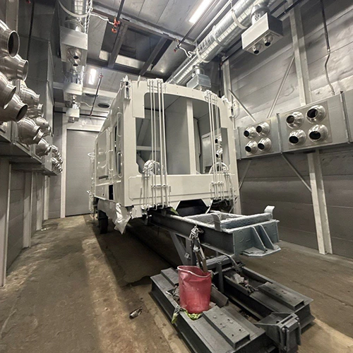
Intake filters clean the air entering the cabin to protect the finish, while exhaust filters trap atomized paint particles leaving the cabin to protect downstream ductwork, exhaust fans, and the outdoor environment. Installing the wrong media in either position can lead to finish defects, restricted airflow, or overspray coating the exhaust stack. Selecting the proper replacement requires matching the exact physical placement, medium design, and airflow resistance specified by your booth manufacturer.
Airflow Pathways: Intake Versus Exhaust Filtration
Differentiating intake and exhaust filter functions begins with tracing the air path through the cabin. A standard industrial or automotive liquid-spray booth relies on balanced airflow to keep airborne contaminants off the wet workpiece and steer overspray away from the painter.
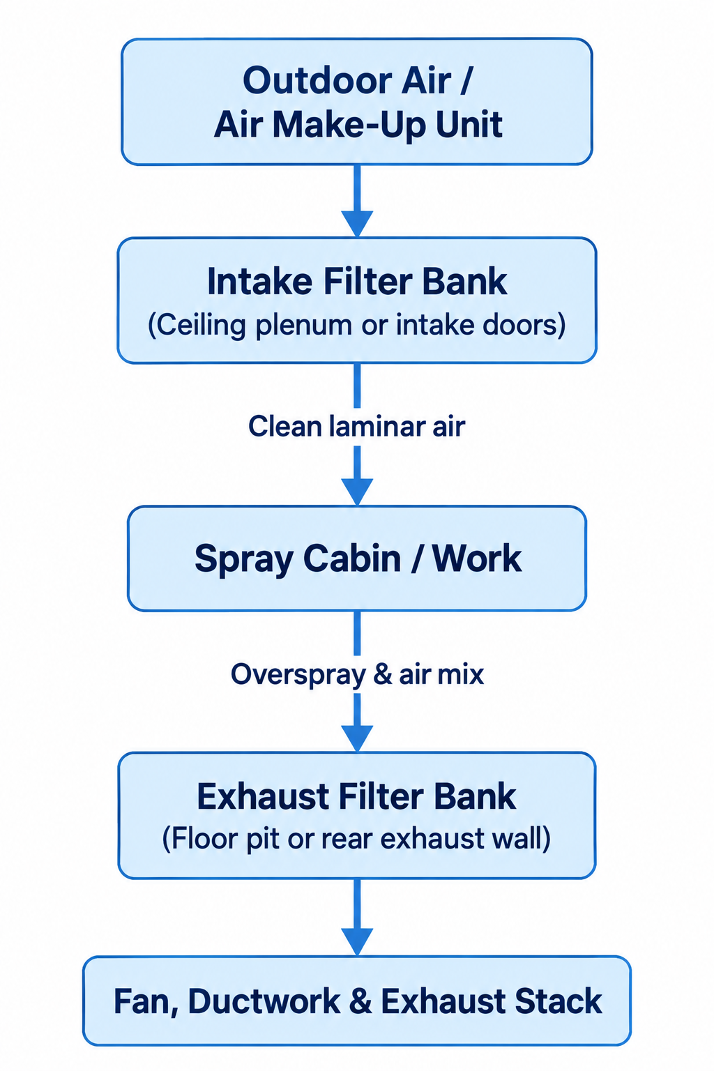
Diagram description
- Outdoor Air / Air Make-Up Unit
- Intake Filter Bank
- (Ceiling plenum or intake doors)
- Clean laminar air
- Spray Cabin / Work
- Overspray & air mix
- Exhaust Filter Bank
- (Floor pit or rear exhaust wall)
- Fan, Ductwork & Exhaust Stack
- Outdoor Air / Air Make-Up Unit → Intake Filter Bank
- Intake Filter Bank → Spray Cabin / Work
- Spray Cabin / Work → Exhaust Filter Bank
- Exhaust Filter Bank → Fan, Ductwork & Exhaust Stack
- Intake Filter Bank → (Ceiling plenum or intake doors): qualifier
- Exhaust Filter Bank → (Floor pit or rear exhaust wall): qualifier
- Outdoor Air / Air Make-Up Unit → Intake Filter Bank (Ceiling plenum or intake doors) → Spray Cabin / Work → Exhaust Filter Bank (Floor pit or rear exhaust wall) → Fan, Ductwork & Exhaust Stack.
- Intake-to-work edge labelled Clean laminar air; work-to-exhaust edge labelled Overspray & air mix.
Intake filtration sits on the positive or incoming side of the airflow loop. Depending on whether your booth is a crossdraft, semi-downdraft, side-downdraft, or full downdraft layout, intake filters mount inside entry doors, overhead ceiling plenums, or dedicated air make-up unit duct connections. Their sole mechanical task is arresting ambient dirt, lint, shop dust, and outdoor particulates before that air enters the active finishing area. High-performance intake media often incorporate a tackifier—a sticky chemical treatment—or a downstream scrim backing that prevents loose filter fibers from breaking free and drifting onto fresh paint.
Exhaust filtration sits on the negative or discharge side of the cabin, located in floor exhaust pits, lower side-wall trenches, or rear exhaust banks. Air entering the exhaust system carries atomized liquid droplets, partially cured coating skins, and dry overspray powder. Exhaust filters capture these wet and dry solids out of the moving airstream before the air reaches the exhaust fan blades, interior duct walls, and the discharge stack.
Particulate Capture Versus Solvent Vapor Control
Standard exhaust media are mechanical particle barriers, not chemical vapor scrubbers. Spray technicians frequently refer to exhaust media as paint arrestor filters, emphasizing their physical role in stopping airborne liquid droplets and solid resin particulates.
Liquid coatings release two distinct components during application: atomized liquid solids (the overspray) and volatile organic compounds (the solvent vapors). Standard overspray dry filters are engineered to extract liquid droplets and tacky solids from the exhaust stream before they coat the fan blades and ductwork. Because these filters rely on physical impingement and mechanical straining, solvent vapors pass directly through them unimpeded.
Under federal workplace standards such as OSHA 29 CFR 1910.107, mechanical ventilation must operate continuously throughout the spraying operation and for a sufficient period afterward to dilute and clear flammable vapors from the booth enclosure. Ordinary particulate exhaust filters help maintain the mechanical efficiency of that ventilation system by keeping the fan assembly balanced and the exhaust passages clear. However, particulate filters do not scrub VOCs, neutralize solvents, or act as an abatement system. Treating exhaust media as a total emissions solution is a critical error; standard filtration alone cannot ensure environmental VOC compliance or eliminate solvent vapor hazards.
Media Construction, Physical Fit, and Static Pressure
Media replacement requires selecting within the manufacturer-approved airflow envelope. Swapping filter types based on guesswork can disrupt cabin pressure balance and starve the exhaust fan.
| Media Category | Typical Mechanical Characteristic |
|---|---|
| Continuous-filament fiberglass pads or rolls | Progressive density; traps wet overspray through the pad depth |
| Multi-layer synthetic polyester (dry or tackified) | Dense fiber structure; often paired with scrim backing |
| Slotted or baffled cardboard (accordion / inertia cells) | Inertial separation; forces air turns to deposit heavy paint runs |
| Pleated surface-loading panels | High surface area; captures dry powders and fine dirt particles |
Physical fit dictates filtration performance. If an exhaust roll is cut one inch too narrow, or if a ceiling pad sags away from its retaining frame, air follows the path of least resistance. Overspray bypasses the filter, collects behind the holding grid, and coats the plenum interior.
Orientation matters just as much as dimensions:
- Many intake blankets feature a distinct upstream and downstream side. Follow the marked airflow direction and the specified backing orientation; reversed installation can impair capture and media retention.
- Exhaust fiberglass blankets use a progressive-density structure—coarser fibers at the face to catch wet droplets, tightening into denser fibers at the backing. Reversing the pad causes rapid surface blinding, cutting airflow long before the depth of the medium is loaded.
Airflow resistance dictates filter longevity and booth safety. Check the booth documentation for its clean-filter baseline and approved replacement trigger, which may be measured in inches of water column (in. w.c.) on a differential pressure gauge or manometer. While tracking differential pressure readings dictates your day-to-day filter change schedule, the initial selection must strictly honor the manufacturer's airflow and velocity envelope.
Do not install unapproved high-efficiency media, such as makeshift HEPA panels or unrated carbon trays, into standard filter frames. These unauthorized retrofits can increase airflow resistance and reduce face velocity; their effect on the fan and motor depends on the installed system.
Replacement Identification Matrix and Sourcing Data
Liquid-spray paint booths require precise media matching to maintain certified face velocity across the work area. Before accessing filter holding grids or interior exhaust channels, follow the manufacturer’s service-isolation instructions and your facility’s authorized lockout/tagout procedure. Never reach behind filter holding grids or service plenums while ventilation fans remain energized.
Use the following framework to document your booth's filtration points:
| Location | Task | Specified Medium | Dimensions & Orientation | Pressure Trigger (Loaded) |
|---|---|---|---|---|
| Intake Doors / Ceiling | Stop ambient dust from entering the cabin | Tackified synthetic polyester mat or pleated panel | Exact cut size (H × W × D); scrim facing into booth | Manufacturer-specified baseline and replacement trigger |
| Air Make-Up Unit (AMU) | Pre-filter raw outdoor intake air | Pleated pre-filters or synthetic pads | Frame rack dimensions; airflow arrow pointing inward | Manufacturer-specified baseline and replacement trigger |
| Exhaust Bank / Pit | Capture wet overspray before exhaust fan | Fiberglass arrestor pad or expanded kraft paper | Roll width × length or pad cut size; skin/backing downstream | Manufacturer-specified baseline and replacement trigger |
| Exhaust Secondary / Stage 2 | Capture fine overspray particulate carryover | High-efficiency fiberglass or multi-pocket bag | Pocket count, depth, and frame dimensions | Differential limit specified by booth manufacturer |
To purchase correct replacements without guesswork, collect the following data from your equipment:
- Manufacturer Nameplate Data: Locate the metal data plate on the booth exterior wall or control panel. Record the manufacturer, model number, serial number, and design CFM.
- Plenum and Frame Measurements: Measure the interior opening of the filter holding tracks or wire grid frames. Use true tape-measure dimensions rather than nominal filter carton labels, which often round up to the nearest inch.
- Media Style: Determine whether the location uses continuous rolls, pre-cut pads, rigid boxed panels, or pocket bags.
- Differential Pressure Gauge Limits: Check the clean-air baseline marked on your manometer or draft gauge to confirm what baseline resistance your fan system expects.
If nameplates are faded or original manuals are missing, provide these physical dimensions, frame styles, and coating types to your equipment representative. To source exact-fit intake or exhaust media for your existing spray enclosure, contact our team to Request a Quote.