
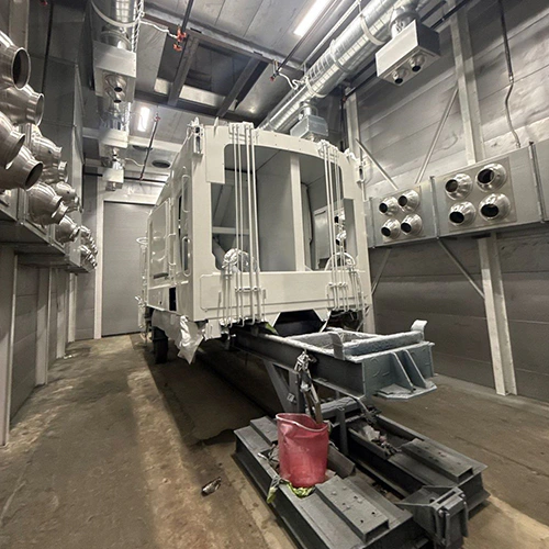
Selecting between an industrial liquid line and an electrostatic powder coating system comes down to the physical properties of your parts, your production throughput, and the space and utilities available in your facility. Neither technology is universally superior. A high-solids polyurethane applied in an automated liquid booth can outperform a poorly cured standard polyester powder in salt spray testing, just as a properly formulated powder system can streamline labor and eliminate solvent emissions on high-volume steel assemblies.
Evaluating the differences early prevents expensive missteps in booth sizing, oven capacity, and electrical infrastructure.
Evaluating Substrate Compatibility and Service Demands
Substrate material dictates your baseline options. Conventional electrostatic thermoset powder coating relies on an electrostatic charge to attract dry particles to a grounded workpiece, which is then heated so the powder melts, flows, and cross-links into a continuous film. The part must withstand the chosen powder’s specified cure cycle without warping, degrading, or outgassing.
Cast iron, structural steel, sheet metal, and aluminum are common candidates, subject to the alloy, construction, and cure cycle. Conversely, heat-sensitive components—such as assembled parts containing rubber seals, pre-greased bearings, solder joints, or composite inserts—are ill-suited for standard thermal cure ovens. While low-cure powders and UV-curable powders exist for engineered plastics and medium-density fiberboard (MDF), they operate within narrow process windows and require dedicated equipment. They do not turn every heat-sensitive plastic or assembled sub-assembly into a viable powder candidate.
Liquid finishing accommodates a broader range of materials:
- Solventborne formulations: Epoxies, urethanes, alkyds, and specialized fluoropolymers that cure at ambient room temperature or under a formulation-specific force-drying cycle.
- Waterborne formulations: Lower-VOC alternatives that reduce solvent handling risks, though most waterborne industrial paints still contain small volumes of co-solvents (such as glycol ethers) that affect drying rates, flash-off times, and facility permitting.
- Non-conductive parts: Plastics, wood, fiberglass, and carbon fiber can be coated with liquid using non-electrostatic application, without relying on conductivity.
| Metals (Steel, Aluminum, Castings) | Powder or Liquid viable |
|---|---|
| Pre-Assembled Units (Seals/Grease) | Liquid preferred (ambient/low-bake) |
| Plastics / Composites / Wood | Liquid standard (low-cure powder requires empirical trials) |
| Non-Conductive Complex Shapes | Liquid standard (bypasses grounding limits) |
Environmental durability depends on the combined performance of the cleaning process, conversion coating, and topcoat chemistry. Neither process compensates for poor surface preparation. Liquid and powder both fail prematurely when applied over mill scale, cutting oils, or flash rust. Specifying corrosion resistance requires defining the full stack: cleaning chemistry, mechanical blasting or chemical etching, conversion layers (such as iron phosphate, zinc phosphate, or zirconium), primer, and topcoat.
Match your finish to the precise substrate, operating environment and cure requirements outlined by your customer or internal testing standard (such as ASTM B117 salt spray, ASTM D4587 accelerated weathering, or chemical wipe resistance).
Application Mechanics, Thermal Profiles, and Facility Constraints
The core operational difference between liquid and powder finishing appears on the shop floor: how the material transfers to the part, how it cures, and how the facility safely manages overspray and exhaust.
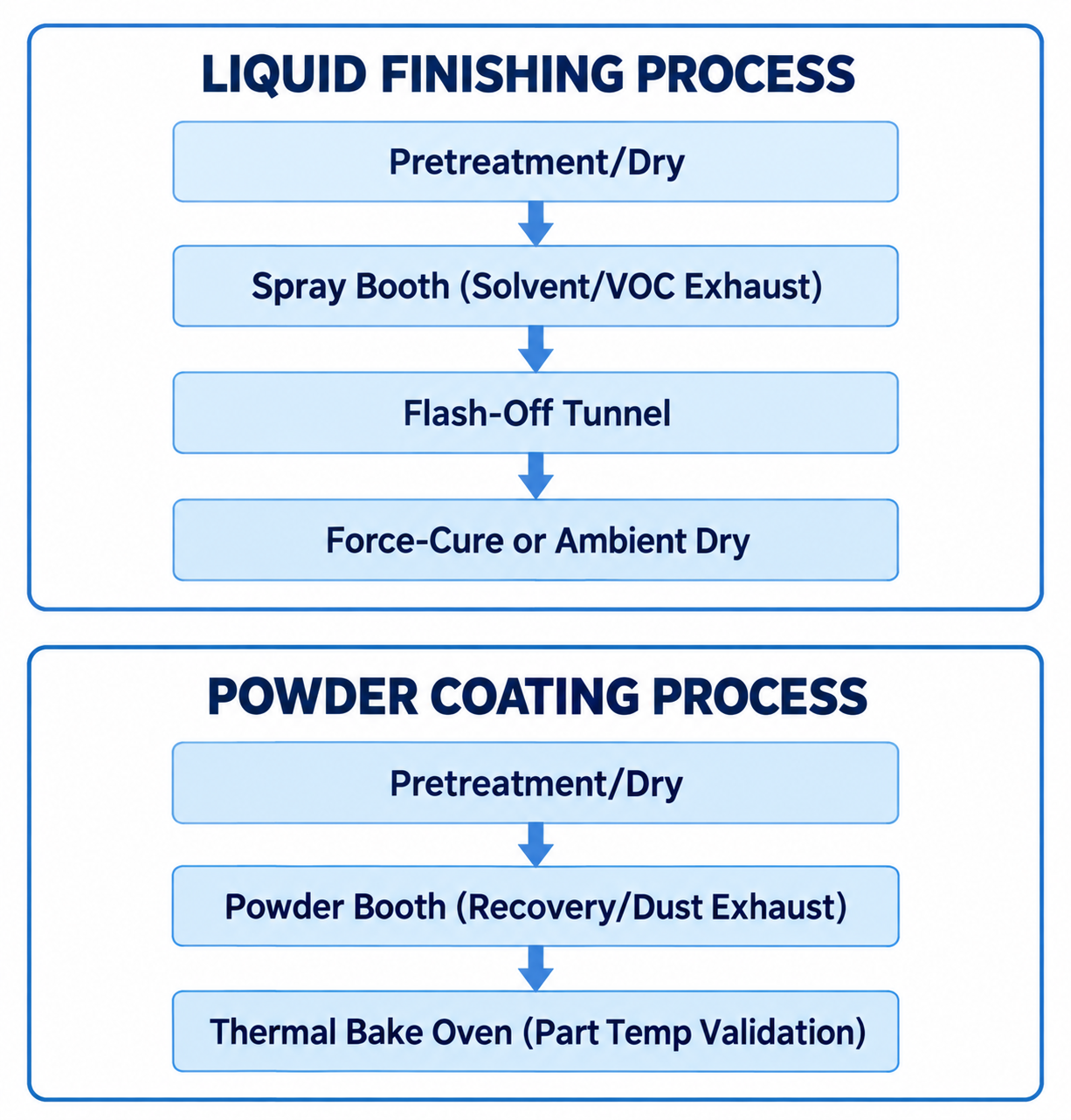
Diagram description
- LIQUID FINISHING PROCESS
- Pretreatment/Dry
- Spray Booth (Solvent/VOC Exhaust)
- Flash-Off Tunnel
- Force-Cure or Ambient Dry
- POWDER COATING PROCESS
- Pretreatment/Dry
- Powder Booth (Recovery/Dust Exhaust)
- Thermal Bake Oven (Part Temp Validation)
- Pretreatment/Dry → Spray Booth (Solvent/VOC Exhaust)
- Spray Booth (Solvent/VOC Exhaust) → Flash-Off Tunnel
- Flash-Off Tunnel → Force-Cure or Ambient Dry
- Pretreatment/Dry → Powder Booth (Recovery/Dust Exhaust)
- Powder Booth (Recovery/Dust Exhaust) → Thermal Bake Oven (Part Temp Validation)
- Liquid: Pretreatment/Dry → Spray Booth (Solvent/VOC Exhaust) → Flash-Off Tunnel → Force-Cure or Ambient Dry
- Powder: Pretreatment/Dry → Powder Booth (Recovery/Dust Exhaust) → Thermal Bake Oven (Part Temp Validation)
Thermal Profiles and Cure Validation
In powder coating, air temperature inside the oven does not equal cure. Powder suppliers specify a technical schedule based on part metal temperature (PMT)—for example, 10 minutes at 380°F PMT.
A heavy, 1-inch-thick steel weldment will take substantially longer to reach 380°F than a 20-gauge sheet-metal bracket running on the same conveyor line. If you set the oven to 380°F and extract the heavy part after 10 minutes, the powder will flow cosmetically but will not fully cross-link, risking poor mechanical performance, adhesion, and corrosion resistance.
Validating a powder line requires running dataloggers with thermal probes affixed directly to the thickest and thinnest sections of the workpiece to bridge the gap between oven setpoint and part temperature.
Some liquid coatings can reduce the need for thermal cure:
- Many two-component (2K) epoxies and polyurethanes cross-link chemically at 70°F (21°C), making them ideal for workpieces too large for standard ovens.
- Force-cure ovens running at lower temperatures accelerate handling times without the prolonged heat soak required by thick metal in powder lines.
- Ambient-cure liquid operations eliminate the initial capital and fuel costs of a thermal cure oven, though they require more floor space for drying and flash-off racks.
Ventilation and Electrical Safety Standards
Both processes present safety hazards that govern equipment design under standards like OSHA 1910.107 and NFPA 33.
| Criteria | Liquid Systems | Powder Systems |
|---|---|---|
| Primary Hazard | Flammable vapors / VOCs | Combustible dust explosion |
| Ventilation Purpose | Control flammable vapor concentration | Prevent explosive dust clouds |
| Classified Electrical | Location-specific vapor hazard rating | Location-specific dust hazard rating |
| Air Management | Outside exhaust / emission treatment | Powder recovery; approved filtered return |
| Oven Interlocks | Purge cycle + exhaust airflow | Heat control + airflow checks |
liquid coating spray booths require ventilation designed for the coating, spray process, exposure, and fire hazards. Exhaust cannot simply be recirculated into the building; it must be ducted outside or directed through emission control equipment such as Regenerative Thermal Oxidizers (RTOs) if local VOC limits demand it.
The supplier must establish the hazardous-location boundaries and suitable electrical equipment for the selected liquid process.
powder coating booths handle combustible dust rather than volatile solvent vapors. Airflow must prevent powder clouds from reaching the Minimum Explosive Concentration (MEC) while containing all overspray within the booth enclosure. Because powder application generally uses a solvent-free material, the exhaust air can often be passed through high-efficiency cartridge filter stages and returned to the plant where the equipment design and applicable requirements permit, cutting winter heating and summer makeup air costs.
However, powder-coating ventilation requirements must be reviewed against the dust hazard and equipment design. The supplier must specify suitable collection, ignition controls, and electrical equipment for the applicable locations.
Geometry, Film Thickness, and Rework Considerations
Part geometry directly influences transfer efficiency and aesthetic consistency across both processes.
Faraday Cage Interference and Film Build
Powder relies on electrical lines of force between the spray gun tip and the grounded part. When a part features deep channels, internal 90-degree corners, louvers, or welded pockets, those electrical lines seek the nearest ground—the exterior edges.
This creates the Faraday cage effect: powder builds heavily on the outside corners while the interior recess remains starved. Possible equipment approaches to validate with the application supplier include:
- Adjusting gun voltage and micro-amperage.
- Switching to specialized nozzles or tribo-charging equipment.
- Manual pre-touch or post-touch guns positioned upstream or downstream of automated loops.
Liquid finishing uses methods such as air spray, HVLP, airless, or air-assisted airless, with or without electrostatic charging. Non-electrostatic application avoids the electrical field effect, but recess coverage still depends on access, atomization, and part geometry.
Powder can achieve useful film build in one application, but the acceptable range and defect risk depend on the product, geometry, and cure. Some liquid formulations require multiple coats and flash-off periods to reach their specified thickness, while high-build products have different limits. For parts requiring thin, precise films—such as fine threaded fasteners, closely toleranced bearing journals, or hinges—compare the specified film build and masking needs for both processes against the dimensional allowance.
| Feature | Liquid Finishing | Powder Coating |
|---|---|---|
| Sharp Edges | Product/application dependent | Product/application dependent |
| Recesses / Pockets | Access/method dependent | Electrostatic recess challenge |
| Film Thickness (Pass) | Per product/application | Per product/application |
| Threaded Tolerances | Check film build/masking | Check film build/masking |
| Class-A Flatness | Formulation/application dependent | Formulation/cure dependent |
Rework, Re-coating, and Field Repair
Repair logistics differ significantly between the two systems:
- Liquid touch-up: Defective areas can be spot-sanded, masked, and sprayed with the same two-component chemistry or a matching air-dry formulation. Blend quality and appearance acceptance depend on the coating, damage, and repair method.
- Powder touch-up: Local powder repair can be difficult because application and heating must suit the complete part and existing film. In-plant rework may involve preparing the surface and applying a second coat (running the risk of intercoat adhesion failure or over-baking the first coat), or using a chemical stripper and starting over. Liquid touch-up is commonly considered for field repairs to powder-coated parts; compatibility, color, gloss, and weathering must be checked against the repair specification.
Building the Finishing System Specification
Before ordering finishing equipment, translate your physical parts, chemistry requirements, and daily throughput targets into a clear engineering brief. Sizing mistakes in booths and ovens cause severe bottlenecks once production begins.
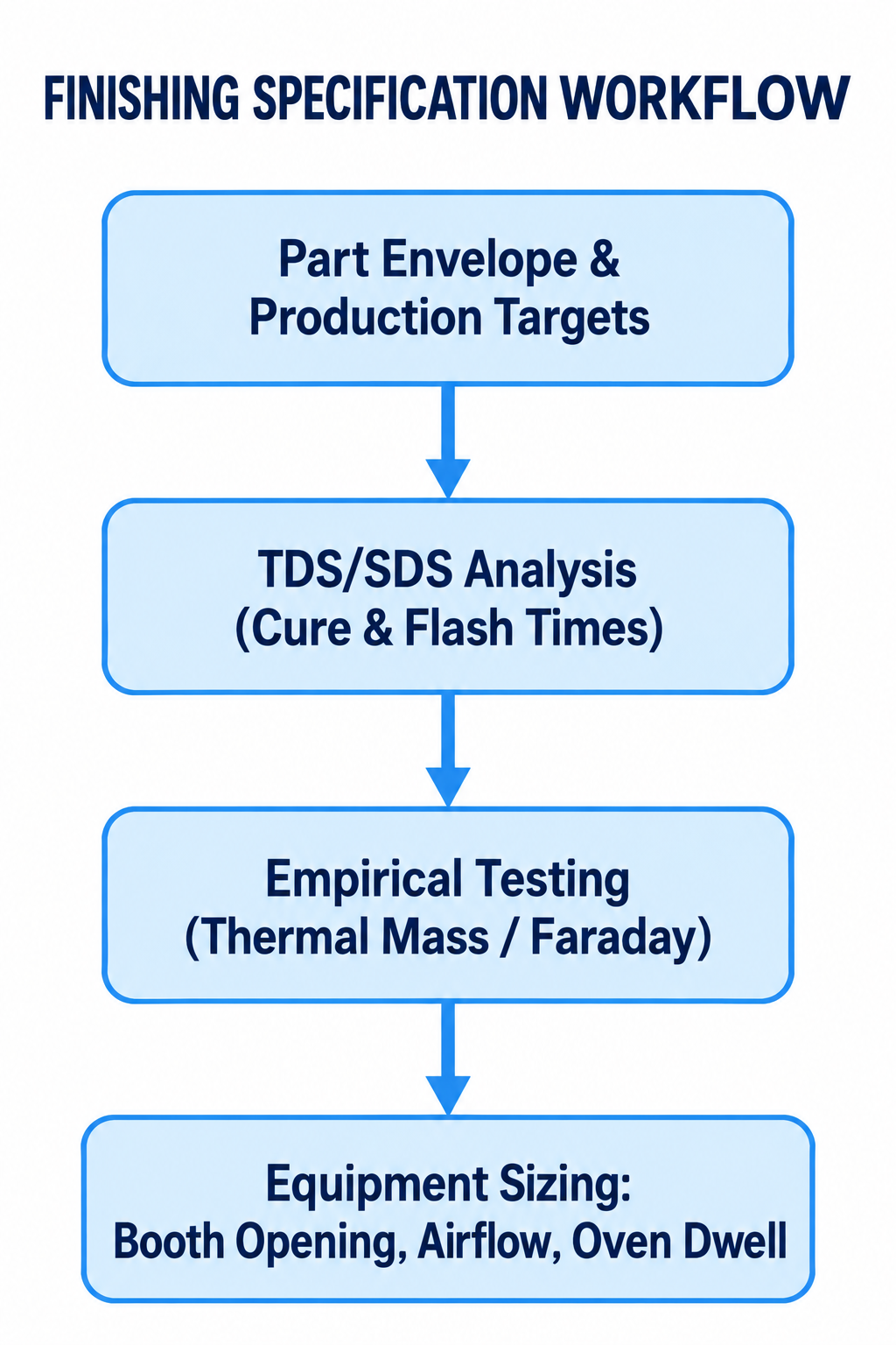
Diagram description
- FINISHING SPECIFICATION WORKFLOW
- Part Envelope & Production Targets
- TDS/SDS Analysis (Cure & Flash Times)
- Empirical Testing (Thermal Mass / Faraday)
- Equipment Sizing: Booth Opening, Airflow, Oven Dwell
- Part Envelope & Production Targets → TDS/SDS Analysis (Cure & Flash Times)
- TDS/SDS Analysis (Cure & Flash Times) → Empirical Testing (Thermal Mass / Faraday)
- Empirical Testing (Thermal Mass / Faraday) → Equipment Sizing: Booth Opening, Airflow, Oven Dwell
- FINISHING SPECIFICATION WORKFLOW: Part Envelope & Production Targets → TDS/SDS Analysis (Cure & Flash Times) → Empirical Testing (Thermal Mass / Faraday) → Equipment Sizing: Booth Opening, Airflow, Oven Dwell.
1. Document the Part Envelope and Production Mix
- Maximum Part Dimensions: Length, width, height, and weight of the largest individual part.
- Presentation to the Gun: How the part hangs on the hook, its orientation, and whether it requires rotation or multi-axis gun articulation.
- Line Speed / Cycle Time: The required parts per hour, which dictates conveyor line speed (feet per minute) or batch booth cycle frequency.
- Substrate Mass Variability: The weight differential between your lightest sheet-metal component and your heaviest structural plate.
2. Extract Data from Coating TDS and SDS
Do not design booths or ovens around generic assumptions. Obtain the Technical Data Sheet (TDS) and Safety Data Sheet (SDS) from the coating manufacturer to identify:
- Flash-Off Time: Mandatory dwell time for liquid solvent evaporation before entering an oven.
- Cure Window: Exact time-at-temperature curves (e.g., 15 minutes at 375°F PMT for powder; 30 minutes at 140°F for force-dried liquid).
- Solvent Percentages and Chemistry: VOC/HAP content in liquid paints for the supplier’s ventilation and emissions review, alongside booth geometry and process demand.
- Transfer Efficiency Benchmarks: Application-specific transfer efficiency, reclaim expectations, and filter loading.
3. Conduct Empirical Validation
Never purchase equipment based on catalog specs alone. Run trial parts through an application lab to document:
- Adhesion and film uniformity on difficult geometries.
- True thermal soak times using thermocoupled data loggers to establish real-world powder cure oven requirements rather than theoretical dwell times.
- Salt spray, cross-hatch adhesion, and impact resistance on test panels prepared using your intended pretreatment chemistry.
Equipment Inquiries and Project Scoping
Converting your process choice into a reliable operating line requires engineering the correct physical containment, airflow, and heating profiles.
Whether planning an integrated overhead conveyor line or standalone batch units, gather your part envelopes, cycle targets, and coating technical sheets, then contact a finishing equipment manufacturer to request an equipment quote built to your production requirements.