
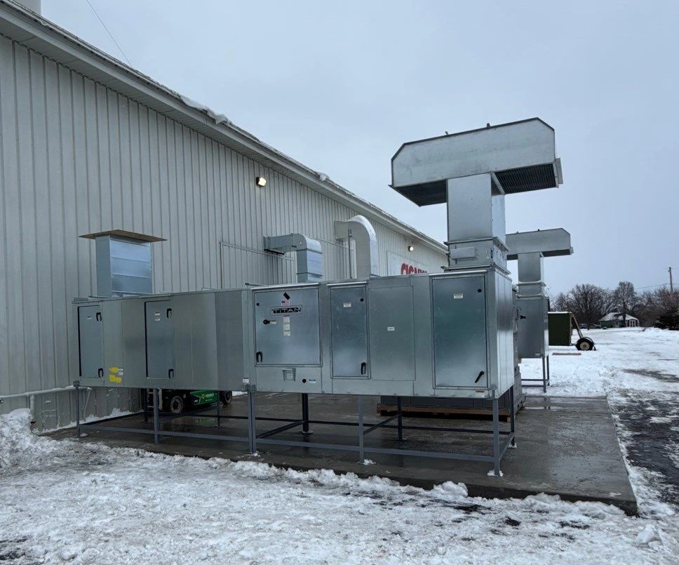
Heating-only air makeup units (AMUs) temper incoming air to support exhaust ventilation; actual AMU capabilities vary by configuration. When ambient summer heat, seasonal humidity shifts, or sensitive coating chemistries disrupt film build and flash times, basic heating is not enough. Achieving repeatable finish quality requires evaluating the coating chemistry, outside design psychrometrics, and booth air handling to determine if true cooling and moisture control are required.
Coating Specifications Dictate Environmental Windows
A coating's Technical Data Sheet (TDS) provides product-specific application, flash and cure conditions; meeting those conditions alone does not guarantee a defect-free finish. Treating these distinct phases as a single general booth setting causes balance issues, because application, flash-off, and thermal cure impose very different thermodynamic demands on the air delivery system.
| Process Phase | Conditions to Review |
|---|---|
| Application | Product-specified temperature, humidity and application conditions. |
| Flash-off | Carrier-removal requirements, local air movement and any product-specified endpoint. |
| Cure | Exact product thermal conditions and approved ventilation/safeguards. |
During application, liquid coatings require a stable dry-bulb temperature and relative humidity (RH) to maintain consistent fluid viscosity and predictable solvent evaporation. If the booth gets too warm or dry, solvents leave the atomized droplet before it strikes the substrate, which can contribute to dry spray or poor leveling; defects alone do not prove the cause.
For waterborne flash-off, surrounding water-vapor pressure influences evaporation. In waterborne systems, water acts as the primary volatile carrier; high ambient humidity can slow water evaporation and extend flash time; finish effects remain product- and process-dependent. For example, the PPG ONEVISIT application instructions for ENVIROBASE High Performance basecoat systems detail how technicians must select specific modifiers and adjust their process based directly on ambient temperature and relative humidity. That specific basecoat process allows either ambient booth airflow or targeted mechanical air movers to reach a visual matte endpoint before clearcoating. Because this chemistry uses specialized modifiers matched to psychrometric conditions, it demonstrates why you cannot apply one universal ambient assumption across every basecoat, clearcoat, or primer in a facility.
Curing introduces a separate thermodynamic profile. Accelerating waterborne drying conditions or baking a cross-linking enamel requires stepping up sensible heat while exhausting sufficient air volume to prevent solvent vapor buildup. A production team must document the specific tolerance bands for each stage directly from the coating manufacturer rather than assuming an average room-temperature target will keep the process compliant.
The Operational Gap Between Standard Air Makeup and Climate Control
A heating-only industrial air makeup unit replaces exhausted air and heats it using its specified direct-fired, indirect-fired or electric arrangement. It replaces the thousands of cubic feet per minute (CFM) removed by exhaust fans and supports the designed booth pressure relationship while warming winter intake air to a set discharge temperature.
| Air Makeup Configuration | Capability to Verify |
|---|---|
| Heating-only | Replacement airflow and heating; no active cooling or moisture removal unless additional equipment is included. |
| Conditioned supply | Actual cooling, moisture removal, reheat and sensing/control provisions; not every system includes all features. |
A heating-only AMU does not actively cool or remove moisture unless additional conditioning equipment is fitted. When outdoor air reaches 95°F with 75% relative humidity, a standard AMU draws that ambient air directly across the filters and into the cabin without modification. Direct-fired burners actually add a small amount of moisture to the airstream as a natural byproduct of fuel combustion, further elevating grain loading during heated cycles.
Systems described as temperature and humidity controlled air makeup units may use the following capabilities; verify what the proposed system includes:
- Sensible Heat Reduction: Lowering dry-bulb air temperature using chilled water or direct expansion (DX) evaporator coils.
- Latent Heat and Moisture Removal: Chilling the intake air below its dew point so water vapor condenses across cooling fins and drains away.
- Process Reheat: Adding controlled sensible heat back into the air after dehumidification to re-establish the precise dry-bulb temperature and lower relative humidity before air enters the spray envelope.
- Dual-Loop Environmental Sensing: Define the required temperature/moisture sensing locations, controls and airflow interfaces for the actual system; dual-location sensing and variable-speed airflow are not universal features.
Standard AMUs work well when ambient conditions fall within the coating window or when applying tolerant industrial solvent chemistries. When process tolerances demand narrow operating bands regardless of external weather, evaluate whether the proposed operating and conditioning approach can maintain those bands.
Site Psychrometrics, Exhaust Loads, and Safety Standards
Sizing an environmental control system requires calculating the physical demands of your location, your booth geometry, and production pacing. The approved outside-air and exhaust arrangements, together with local climate conditions, drive conditioning loads; do not infer an operating mode from the coating category.
- Site weather design conditions selected for the project
- Documented ventilation load and supply requirements
- Part, lighting, enclosure and process loads
- Applicable OSHA, installation, electrical and environmental requirements
- Equipment-specific safeguards and approval scope
Climate and Load Dynamics
Have the equipment engineer select local weather design conditions and capacity criteria appropriate to the project. Cooling and moisture-control loads depend on airflow and the difference between entering and required conditions. For an applicable cross-section using average velocity, volume flow is:
Air Volume (CFM) = Cabin Cross-Sectional Area (sq ft) × Target Air Velocity (FPM)
The required cooling and any condensation depend on the actual entering conditions, airflow and coating-specific supply target. Production factors add further thermal load:
- Part Mass and Entry Temperature: Heavy structural steel weldments or cast parts coming directly from an unconditioned staging yard or pre-wash line carry sensible heat straight into the booth air.
- Enclosure Integrity: Repeated vehicle door cycles, large roll-up curtain cycling, and conveyor pass-through openings draw ambient plant air into the controlled cabin.
- Process Modes: Transitioning from an open spray mode to an accelerated flash cycle changes system requirements instantly. Review control response and equipment cycling limits across the proposed operating modes.
Safety and Regulatory Boundaries
Any system handling conditioned paint booth air must operate within the framework of OSHA spray finishing requirements. The federal standard outlined in 29 CFR 1910.107 establishes strict baselines for ventilation reliability, hazardous location electrical ratings, and fire protection.
OSHA rules treat liquid spray processes and dry powder application under distinct hazard categories. Section (g)(6) requires removal of deposits before alternating specified materials whose combination may promote spontaneous ignition; (b)(5)(vi) restricts alternating use of filters for such combinations. Section (j) addresses safeguards for the covered drying and curing arrangements, including applicable ventilation and interlocks. Section (l) sets powder ventilation, grounding, and housekeeping requirements to mitigate combustible dust hazards.
These federal rules set minimum operating thresholds; they do not serve as a complete local engineering approval. Installation authorities and insurers may apply different requirements and code editions, including relevant NFPA and mechanical provisions that govern whether air recirculation loops, energy recovery wheels, or automated dampers are permissible on a given line.
Comparing Cooling, Dehumidification, and Control Architectures
Selecting the mechanical architecture for climate-controlled finishing systems involves balancing capital expenditure, operational footprint, utility availability, and modulation responsiveness. No single mechanical platform fits every booth envelope.
| Parameter | Direct Expansion (DX) Refrigeration | Central Chilled Water Loop | Desiccant Dehumidification Wheels |
|---|---|---|---|
| Applications to Evaluate | Standalone booths or independent schedules; verify sensible and latent capacity | Shared utilities or existing chiller capacity; verify available capacity and distribution | Processes requiring moisture removal beyond the proposed cooling approach |
| Cooling & Moisture Control | Uses dedicated compressors and condensing units; steps compressors or runs variable-speed systems | Circulates utility chilled water through modulated cooling coils | Passes process air through a desiccant arrangement with its specified regeneration source |
| System Modulation | Digital scroll compressors or hot-gas bypass provide stepwise or continuous load matching | Modulating 2-way or 3-way control valves deliver fine linear tracking across varying CFM | Modulates wheel rotation speed and reactivation heat to track deep moisture removal |
| Infrastructure Demands | Dedicated outdoor condensing footprint, refrigerant lines, high localized electrical draw | Central mechanical plant, distribution piping, primary/secondary loop circulation pumps | High-capacity thermal regeneration heat source (gas/steam), substantial mechanical cabinet space |
| Maintenance Profile | Refrigerant circuit service, compressor servicing, standard coil washing | Central plant maintenance, valve packing, glycol concentration monitoring | Wheel seal replacement, desiccant drive mechanisms, high-heat reactivation exhaust servicing |
Engineering Considerations
- DX vs. Chilled Water: Direct expansion systems work well for facilities without a central chiller plant. While DX systems can struggle with rapid load fluctuations across large CFM swings, digital scroll compressors and inverter-driven systems have narrowed that gap. Chilled water systems provide smooth, linear modulating control via precision water valves, making them well suited for operations running multiple booths from a shared utility plant.
- Mechanical Cooling vs. Desiccant Dehumidification: Mechanical cooling coils condense water out of the air by dropping its temperature below the dew point, which may require reheat if the resulting supply temperature is below the application target. Desiccant wheels extract moisture directly through chemical adsorption without needing deep refrigeration temperatures. Compare desiccant equipment cost, regeneration energy and capacity against the actual moisture-control target; no universal dew-point threshold selects the technology.
- Recirculation Safety vs. Single-Pass Efficiency: Recirculating conditioned air during spray modes saves substantial thermal energy, but it demands robust engineering controls. Any return-air or energy-recovery arrangement requires equipment-specific design and review under the applicable requirements and code edition. Do not treat vapor monitoring, a HEPA/carbon filter label or a generic interlock list as permission to recirculate spray exhaust.
Information Needed for an Equipment Engineering Review
Procuring an environmental control package requires translating your facility's physical constraints and chemical requirements into documented performance criteria. Vague targets can leave sizing and control performance unverified.
Gather these four core packages to build an actionable engineering brief:
- Coating technical requirements
- Site climate and design conditions
- Booth air-handling data
- Facility utility capacities
- Submit these together for equipment engineering review.
- Coating Technical Requirements: Gather the exact product data sheets for your primers, basecoats, and clearcoats. Note the required dry-bulb temperature range, relative humidity limits, minimum and maximum air velocities, and flash-off timing windows.
- Geographic Weather Extremes: Identify your site’s location and provide available weather data; have the engineer select appropriate design conditions and capacity criteria rather than relying on monthly averages.
- Booth Geometry and Ventilation Metrics: Document the physical dimensions of the booth cabin, filter ceiling area, exhaust style (downdraft, semi-downdraft, or side-downdraft), total design airflow in CFM, and static pressure ratings across clean and dirty filters.
- Facility Infrastructure and Cycle Rates: Define available utility services, including natural gas line pressure, incoming electrical service (voltage, phase, and available breaker capacity), and central chilled water or steam availability. Outline your production schedules, cycle times, entry doors frequency, and the maximum mass, material, and temperature of parts entering the booth.
When you are ready to evaluate equipment configurations for your application, request a finishing equipment quote with your process parameters, facility layout, and coating performance data to discuss an engineered system designed for your operational requirements.