
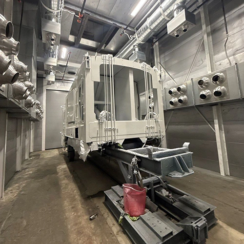
An automotive paint booth is an engineered enclosure designed to control airborne contamination, exhaust hazardous overspray, and create a predictable environment for applying and curing vehicle finishes. It bridges the critical production phase between prep work and final assembly.
Investing in a spray booth requires looking past catalog marketing terminology. Understanding how mechanical airflow paths, filtration media, and pressure dynamics interact allows facility owners and project engineers to evaluate technical specifications accurately and select equipment that fits their building infrastructure.
The Refinishing Workflow: Defining the Booth's Role
The paint booth isolates the liquid coating application from the rest of the shop. Surface preparation—such as grinding, filler work, primer sanding, and masking—generates massive amounts of heavy particulate that must remain outside the spray cabin. The booth does not replace substrate prep, nor does it correct errors made during surface cleaning.
Inside the cabin, the system performs two safety and quality functions:
- It introduces filtered air to prevent airborne dust, lint, and debris from settling into wet basecoats and clearcoats.
- It captures atomized overspray and exhausts volatile organic compounds (VOCs) and flammable solvent vapors away from the technician and the vehicle.
A spray booth does not replace personal protective equipment (PPE). Ventilation must be designed and maintained to control airborne solvent concentrations, particulate filters capture only solid and liquid resin droplets—they do not eliminate toxic gases, solvent vapors, or isocyanate molecules. Respiratory protection and other PPE must be selected through the applicable exposure assessment and protection program.
Core Components: Tracing the Air Path from Intake to Exhaust
Air moving through a paint booth follows a continuous mechanical train. Recognizing each component in the sequence makes it easy to read mechanical drawings and identify operating issues.
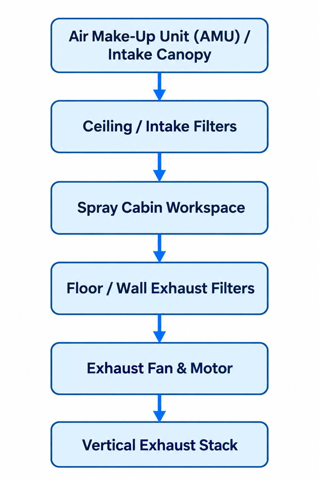
Diagram description
- Air Make-Up Unit (AMU) / Intake Canopy
- Ceiling / Intake Filters
- Spray Cabin Workspace
- Floor / Wall Exhaust Filters
- Exhaust Fan & Motor
- Vertical Exhaust Stack
- Air Make-Up Unit (AMU) / Intake Canopy → Ceiling / Intake Filters
- Ceiling / Intake Filters → Spray Cabin Workspace
- Spray Cabin Workspace → Floor / Wall Exhaust Filters
- Floor / Wall Exhaust Filters → Exhaust Fan & Motor
- Exhaust Fan & Motor → Vertical Exhaust Stack
- Linear directed flow: Air Make-Up Unit (AMU) / Intake Canopy → Ceiling / Intake Filters → Spray Cabin Workspace → Floor / Wall Exhaust Filters → Exhaust Fan & Motor → Vertical Exhaust Stack.
1. Air Intake and Supply
Non-pressurized booths pull replacement air directly from the surrounding shop floor through intake filters using the suction generated by the exhaust fan.
Pressurized systems introduce fresh air actively through an Air Make-Up Unit (AMU). An AMU houses weather louvers, intake pre-filters, a direct-fired gas burner or heat exchanger, and a motorized supply blower. The AMU draws outdoor air, tempers it to the target spraying or baking temperature, and pushes it directly into the booth ceiling plenum.
Note on shop pressure: Booth pressure and building pressure are separate variables. A pressurized booth controls its internal balance relative to the shop; building pressure can still affect replacement-air and exhaust performance.
2. Cabin Structure and Lighting
The cabin consists of interlocking single-skin or double-wall insulated steel panels sealed along all seams. Observation windows use tempered safety glass.
Lighting fixtures must provide shadow-free illumination across all vehicle surfaces (with illumination verified against the selected booth and task requirements). Fixtures must be sealed, rated for hazardous locations as required by their proximity to the spraying envelope, and serviceable from outside the cabin or through sealed internal access doors.
3. Intake and Exhaust Filtration
Understanding the division between intake and exhaust filtration is fundamental to diagnosing finish defects and booth performance.
- Intake filters: Positioned in the ceiling plenum or intake doors, these diffusion media trap ambient dust particles down to small micron levels before the air enters the workspace.
- Exhaust filters: Located in the floor pit, side exhaust walls, or rear bulkhead, these dense fiberglass or paper media arrest sticky paint particulate to protect the exhaust fan blades, ductwork, and outdoor environment from paint buildup.
4. Cabin Pressure vs. Airflow Direction
Airflow direction describes the geometric path air takes (top to bottom, or end to end). Cabin pressure describes the mechanical force inside the enclosure relative to the surrounding room.
Booth pressure is determined by the supply and exhaust balance—the ratio between the volume of air introduced and the volume pulled out.
- Negative Pressure: The exhaust fan pulls slightly more cubic feet per minute (CFM) than the intake supplies. If a door gasket fails, air rushes into the cabin, pulling shop dust onto the wet finish.
- Positive Pressure: The supply and exhaust are balanced to the manufacturer-specified positive pressure. Air gently pushes outward through door seams, keeping external shop contamination out of the cabin.
Where fitted, Variable Frequency Drives (VFDs) can modulate the fan motors to maintain the specified balance as filters load with paint.
5. Exhaust Fans, Stacks, and Interlocks
Exhaust fans and motor arrangements must suit the spray-finishing installation. The supplier should verify duct routing, discharge location, and separation from building air intakes against the applicable requirements.
Ask the supplier how the controls prevent spraying without the required ventilation and how airflow loss is detected.
Airflow Geometries: Comparing Direction and Layout
When evaluating automotive paint booth options, shop owners encounter a confusing array of catalog labels: crossdraft, semi-downdraft, side-downdraft, modified downdraft, and full downdraft. Manufacturers do not use standard naming conventions. Always evaluate the physical intake and exhaust locations on an engineering drawing rather than relying on model names.
| Configuration | Intake Location | Exhaust Location | Structural Requirements | Airflow Characteristics |
|---|---|---|---|---|
| Crossdraft | Front vehicle doors | Rear wall bulkhead | Flat concrete slab | Horizontal; overspray sweeps over panels behind the spray zone |
| Semi-Downdraft | Forward ceiling plenum | Rear wall bulkhead | Flat concrete slab | Diagonal; air sweeps down and back across vehicle |
| Side Downdraft | Full ceiling plenum | Lower sidewall plenums | Flat concrete slab | Down and out toward lower side exhaust plenums |
| Full Downdraft | Full ceiling plenum | Center pit under floor grating | Excavated concrete pit or raised steel basement | Ceiling-to-floor direction toward floor exhaust |
Crossdraft and Ceiling-Fed Arrangements
Crossdraft booths introduce air through the front entry doors and pull it straight across the length of the car to an exhaust bank at the far end. Because air travels horizontally, overspray atomized at the front bumper is carried past the doors, quarter panels, and rear bumper before it reaches the exhaust filters.
Semi-downdraft (often called modified downdraft) shifts the intake to the front section of the ceiling. Air moves downward into the workspace and sweeps back toward the rear exhaust wall on a diagonal path. The ceiling intake changes the path of incoming air; actual cleanliness and overspray movement depend on filtration, loading, and booth operation. Both designs install easily on standard, flat concrete floors without excavation.
Floor and Side-Exhaust Arrangements
Full downdraft introduces air across the entire ceiling filter bank and pulls it straight down through floor grating. The intended ceiling-to-floor path directs overspray toward the floor exhaust, though the vehicle and operator can disturb local airflow. However, full downdraft systems require concrete pit excavation or an elevated cabin floor with entry ramps.
Side-downdraft systems provide an alternative when concrete cutting is impossible. Air enters uniformly through a full ceiling plenum and is drawn down toward the floor, where it splits and exits through exhaust plenums built into the bottom of the side walls. This layout provides clean vertical airflow down to bumper level while sitting on an existing concrete floor, though the interior wall plenums slightly narrow the usable workspace.
Evaluating Specifications: Technical Questions for Equipment Suppliers
Specifying a spray booth requires balancing production throughput, vehicle sizes, coating chemistry, and local utility capacity. Consult an engineering-focused paint booth dimensions guide to verify clearance around open doors, hoods, and vehicle beds rather than relying on rough exterior footprints. Ask the supplier to verify the working clearance needed for the vehicle, open panels, operator movement, and selected application equipment.
When reviewing equipment proposals, address these direct technical questions to your supplier:
1. Ventilation and Airflow Compliance
- What is the calculated operating air velocity (in feet per minute) across the cross-sectional area of the empty cabin?
- Does the supplied CFM meet mandated spray-finishing ventilation requirements based on cabin cross-sectional velocity and the specific coating transfer efficiency?
- What total static pressure is the exhaust fan engineered to overcome, accounting for duct elbows, roof penetrations, and fully loaded exhaust filters?
2. Make-Up Air and Thermal Cycles
- Is the AMU engineered for 100% outside air during spray cycles, and does it provide a dedicated recirculation mode for bake cycles?
- What is the maximum temperature rise capability (delta T) of the burner during freezing outdoor winter conditions?
- What natural gas or propane supply pressure (in PSI or inches of water column) and volume (BTU/hr) are required at the unit connection?
3. Electrical and Facility Integration
- What is the total connected electrical load (running amps and breaker requirements) for fans, burners, and interior lighting across your building’s voltage supply (e.g., 208V, 240V, or 480V 3-phase)?
- Where are the hazardous area classification boundaries located around the booth doors and exhaust stack relative to local electrical codes?
- Does the controls platform use open-architecture components (relays, standard digital controllers, or accessible PLCs) or proprietary electronics?
4. Filtration Media and Maintenance
- Are the intake ceiling diffusion blankets and exhaust arrestor pads standard off-the-shelf industrial sizes, or do they require proprietary-cut framing?
- Does the control panel include a mechanical differential pressure gauge (manometer) or digital pressure transducer to support filter-condition checks against the manufacturer’s replacement criteria?
Once you compile your target vehicle envelope, utility limits, and production targets, you can contact PaintBooth.com to request an equipment quote matched directly to your facility. Preparing these facility constraints ahead of time helps the supplier validate airflow, clearance, and safety controls for your refinish operation.