A quoted paint booth that matches your shop floor's square footage can still fail to fit your facility. A quoted interior cabin size identifies only the specified working space, not the physical steel footprint, the clearance required to swing open the doors, or the vertical room demanded by exhaust fans.
While choosing booth size around production establishes how many parts you spray per shift and whether batching makes sense, spatial measurement determines whether that booth can physically exist and operate inside your building. Converting a facility survey into a drawing-ready equipment brief requires separating interior capacity from installed exterior geometry across four distinct spatial envelopes.
The Four Envelopes That Define Paint Booth Fit
A single set of dimensions cannot describe a spray booth. To prevent ordering errors, break your site measurements into four separate measurement categories:
| Measurement Category | What It Establishes |
|---|---|
| Work envelope | Part, support hardware and operating reach |
| Working interior | Usable space inside the selected booth configuration |
| Clear door opening | Pass-through width and height at entry and exit |
| Overall installed footprint | Equipment exterior plus required service and installation space |
1. Work Envelope
This is the physical profile of the largest workpiece you spray, measured together with its support hardware. It accounts for carts, fixtures, open vehicle panels, and technician gun standoff distance.
2. Working Interior
This is the usable, unobstructed volume specified for the booth configuration, excluding filter chambers and other obstructions. It defines the space available for the work and operator while maintaining the designed airflow path.
3. Clear Door Opening
This is the true pass-through dimension of the entry and exit points with the doors fully open in their intended operating position. Frame hardware, sweep seals, roll-up door bottom bars, and structural jambs regularly reduce this figure below the booth's interior width and height.
4. Overall Installed Footprint
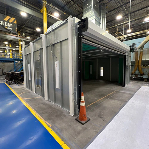
This is the total exterior three-dimensional volume occupied by the cabin, air intake plenums, exhaust towers, drive motors, air make-up ducting, and mandated service access zones. Equipment cut sheets differentiate working and overall dimensions because structural columns, lights, and filter chambers can increase the exterior dimensions.
Confirm dimension ordering on the drawing: Width (W), Height (H), and Depth/Length (D or L).
- Width: Left-to-right facing the entrance doors.
- Height: Finished floor to the specified interior ceiling or exterior equipment high point.
- Depth/Length: Front-to-rear distance using the drawing’s stated endpoints.
Review quotes carefully to confirm whether "Length" includes the rear exhaust plenum or just the clear filter line. Use the model drawing to establish the added depth and height of intake plenums and exhaust cabinets.
Measuring the Workpiece in Motion and in Process
Static tape-measure numbers on a resting part lead to undersized booths. A structural frame or machinery chassis occupies a much larger footprint the moment it enters production.
- Measure the workpiece in its process position, including open doors or rotating arms.
- Include the actual cart or skid height.
- Check the caster sweep during turns.
Part Supports and Carriers
Measure parts on the actual transport gear used during the coating cycle:
- Carts and dollies: Measure from the shop floor to the lowest part surface. The caster frame adds height that eats into vertical clearance under ceiling filter banks.
- Overhead hooks and racks: Measure from the hook eye to the top of the part. If your facility uses an overhead monorail or bridge crane, that rigging space must fit under the booth's structural lintel.
- Pallet jacks and forklifts: If material handling equipment enters the booth cabin, measure the outer fork width, mast height when raised, and operator platform dimensions.
Articulation and Rotating Geometry
Measure the workpiece in its widest and tallest process states. Vehicle hoods, tailgates, enclosure doors, and access panels swung outward increase the part's effective envelope by several feet. If parts sit on welding positioners, rotisseries, or tilt-tables to allow horizontal spraying, swing the mechanism through its full 360-degree range and measure the outer diagonal sweep.
Realistic Operator Clearance
Avoid arbitrary clearance rules like "add three feet everywhere." Working clearance must accommodate specific physical operations:
- Gun Standoff: Use the standoff specified for the selected gun and coating, plus the length of the technician's forearm and the trailing hose whip.
- Operator Ergonomics: Check the technician’s reach and stance for high vertical faces while maintaining the specified spray technique and keeping hose lines off wet coatings.
- Access Equipment: If the work requires elevated access, will the technician use a step stand, mobile platform, or rolling ladder? A rolling aluminum platform requires its own floor footprint alongside the part, plus room for the painter to pass without rubbing safety rails against wet film.
Validating Door Clearances and Facility Travel Paths
A booth cabin might fit inside your shop bay, but you still need to get parts into it—and the booth components themselves through your exterior walls during delivery.
- Main aisle: Check crane posts and other obstructions.
- Turn: Check the swept path of long parts.
- Door swing zone: Check that door leaves clear aisles.
- Clear opening: Account for jambs, seals and other obstructions.
Clear Opening vs. Frame Dimensions
Confirm whether a door spec sheet listing an "8x8 door" describes the clear opening or nominal frame size. Measure the clear opening:
- Hinged swing doors: Measure the face-to-face distance between the inner door leaves when opened to 90 degrees. Hinge knuckles, panic hardware, and interior latch handles protrude into the lane.
- Roll-up doors: Measure from the finished floor to the lowest point of the bottom bar when the curtain is fully coiled into the overhead drum. Measure width between the interior guide tracks, not the rough wall cutout.
- Thresholds and ramps: Floor-recessed exhaust pits can allow flat entry; raised-floor exhaust designs may require drive-over ramps. Confirm the threshold and floor arrangement for the selected model. Ramps change the breakover angle of long-wheelbase carriers, creating high-centering risks.
Approach Corridors and Turning Sweeps
Parts rarely approach a spray booth on an infinite centerline. If the access lane forces a 90-degree turn directly in front of the door, the clear opening must be substantially wider than the part to allow for the diagonal swing:
- Measure aisle width from the booth door threshold to the nearest obstruction (building column, assembly bench, or adjacent wall).
- Calculate the swept path of long extrusions or trailers. A 20-foot-long part on a steerable cart sweeps an arc wider than its static profile during a turn.
- Forklift tail-swing requires dedicated aisle width outside the booth doors when spotting heavy skids inside the cabin.
Door Swing Footprints
Map where the booth doors live when opened:
- Outward-swinging bi-fold doors, sweeping a broad arc across the exterior shop floor. Check whether that arc encroaches into marked pedestrian lanes, hits structural columns, or blocks emergency exits.
- Roll-up doors eliminate exterior swing footprints but require overhead room for the coil barrel, which can collide with building structural steel or intake air ducts.
Equipment Delivery Path
Review the path the booth takes to reach its slab:
- Booth wall panels, plenum structures, and fan housings arrive on flatbed trailers in large modular sections.
- Check your facility's overhead receiving doors, interior roll-up access, and forklift capacities to ensure components can reach the installation pad without cutting building walls.
Reserving Overhead Space and Mechanical Clearances
The space above and around a spray booth is filled with mechanical infrastructure. Overhead equipment collisions can constrain installation even when floor space is available.
- Map the ceiling deck or roof truss above the booth.
- Locate duct penetrations, exhaust fans and the air make-up unit.
- Include the cabin, plenums and motors in the equipment envelope.
- Reserve maintenance access from the finished floor around the equipment.
Overhead Obstruction Mapping
Measure ceiling height starting from the highest point of your finished slab, checking multiple locations across the bay to catch floor slope. Record the bottom elevation of every overhead feature:
- Lower chords of structural roof trusses or bar joists
- Bridge crane runways, hoists, and electrification bars
- Suspended gas, air, water, and process piping
- Conduit racks, bus ducts, and high-bay light fixtures
- Fire sprinkler lines and discharge heads
Exhaust fans, discharge transitions, and roof-mounted air make-up units (AMUs) require significant vertical clearance. Early coordination of paint booth exhaust planning ensures your ductwork does not intercept structural joists, crane tracks, or rooftop HVAC units on its run to the roof penetration.
Structural and Fire Setbacks
Confirm perimeter clearances against the equipment drawings and applicable spray-finishing and local fire requirements:
- Combustible Wall Clearances: For spray finishing covered by OSHA 1910.107(b)(9), a clear space of at least 3 feet on all sides must be kept free from storage or combustible construction. Confirm additional requirements and any permitted arrangements with the authority having jurisdiction.
- Sprinkler Discharge: Installing a booth underneath existing facility sprinklers creates an obstruction. Have the fire-protection designer assess required booth, filter-space and duct protection under the applicable standards.
Service and Maintenance Envelopes
A booth must be maintainable after sign-off. Ensure you leave room for regular operations:
- Exhaust Fan Access: Belt-driven exhaust fans require access to motors, drive belts, and bearings for routine maintenance and tensioning.
- Filter Replacements: Intake ceiling filters slide out downward or through ceiling latches. Exhaust dry filters, roll media, or water wash components require clear access lanes to pull loaded, paint-caked filters without damaging fresh walls.
- Electrical Controls: Applicable electrical rules require clear working space around equipment; have the electrical designer establish the required depth, width and height for the panel voltage and installation conditions.
- Reviewing the manufacturer site requirements confirms the precise perimeter and roof clearances mandatory for your specific model.
- Comparing different industrial paint booth configurations—such as top-mounted mechanicals versus rear-tower exhaust—lets you choose a layout that adapts to low ceilings or tight corners.
Site Measurement and Verification Worksheet
Use this worksheet to gather actual facility dimensions before submitting layout drawings or requesting quotes. Mark unknown conditions explicitly and capture photos of every measuring tape reading.
| Envelope Category | What to Measure and Include | Dimension (Include Units) | Verification Status (Field / Drawing / Photo) |
|---|---|---|---|
| Workpiece Profile | Maximum length, width, and height of the raw part | ||
| Transport Hardware | Floor-to-part height on cart, skid, or pallet; hook drop; caster spread | ||
| Dynamic Work State | Outer dimensions with all doors, access hatches, and panels swung fully open | ||
| Operator Space | Lateral standoff clearance required for gun reach, painter pass-by, or step platforms | ||
| Usable Interior Target | Resulting required working interior: Width × Height × Depth | ||
| Entry Door Clear Opening | Unobstructed pass-through width and height (subtracting stops, tracks, and sills) | ||
| Entry Corridor & Swing | Aisle width facing entrance, 90-degree turning radius, door leaf swing perimeter | ||
| Available Floor Footprint | Usable concrete slab length and width dedicated to the booth and staging | ||
| Lowest Overhead Point | True distance from finished slab to lowest truss, crane rail, light, or sprinkler line | ||
| Duct Penetration Path | Distance and line-of-sight from fan exhaust deck to roof deck or exterior wall | ||
| Perimeter Clearances | Distance between booth cabin walls and adjacent facility walls, structural columns, or equipment | ||
| Control & Service Access | Required working space for electrical panels and model-specific access for motor service and filter removal | ||
| Facility Ingress Route | Smallest overhead door, interior gate, and aisle between the loading dock and the slab |
Data Verification Checklist
- Units of Measurement: Confirm that all entries clearly specify feet, inches, or millimeters. Convert measurements consistently when combining fractions and decimals across documentation.
- Datum Points: Establish whether vertical measurements are taken from the raw slab, finished coatings, or raised foundation curbs.
- Photos as Evidence: Take wide-angle establishing shots of the bay, floor-to-ceiling elevation shots, and close-up photos of tapes held against ceiling obstructions and floor joints.
- Drawing Revision Control: Record the date, revision number, and author of any facility CAD layouts used to pull dimensions.
Documenting these spatial limits transforms a generic inquiry into an actionable engineering brief. To move your project from field measurements to verified engineering drawings, request a layout and equipment quote that reflects the exact clearances of your workpieces and facility.