
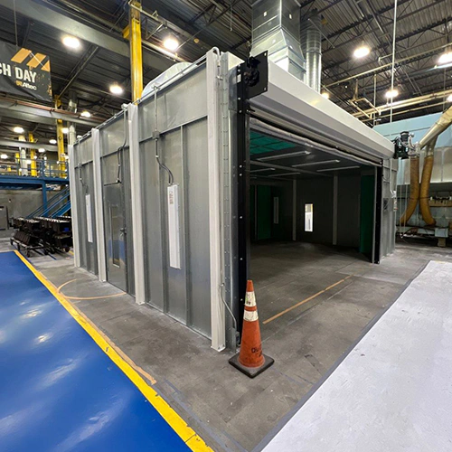
An industrial paint booth is not a self-contained appliance. It is an air-handling machine tied directly into your building's roof, structural steel, electrical switchgear, and supply air systems.
Buyers often evaluate a booth proposal strictly by chamber footprint and upfront price, treating the exhaust system as an afterthought to be handled during assembly. That oversight routinely leads to expensive field retrofits, compromised booth airflow, failed fire marshal inspections, and unbudgeted trade work. Before issuing a purchase order or pouring concrete, facilities leads must verify how the exhaust system interfaces with the building envelope.
The Exhaust Path: From Spray Zone to Outdoors
Exhaust ventilation in a spray environment serves two distinct purposes: containing overspray to maintain product quality and purging flammable or toxic vapors to protect personnel and property. Air follows a continuous mechanical path from the work area to the exterior atmosphere.
Exhaust path: Working chamber → arrestor filter bank → exhaust plenum and fan → ductwork → exterior discharge.
- The capture zone: Air enters the working area—either drawn through intake filters from the plant or supplied via an overhead plenum—and sweeps past the part being coated. The airflow velocity must be high enough to capture bouncing overspray and solvent drift without disturbing the atomized spray pattern.
- The particulate arrestor bank: Overspray-laden air is pulled through dry particulate exhaust filters located in the back wall (crossdraft) or pit/side exhaust plenums (downdraft). These arrestor pads capture liquid droplets and solid pigment particles. They do not arrest volatile organic compounds (VOCs) or solvent vapors.
- The exhaust fan: With particulate reduced by the filters, the air stream enters the exhaust plenum. A dedicated fan—typically a belt-driven or direct-drive tubeaxial fan equipped with spark-resistant non-ferrous blades and a motor isolated outside the flammable airstream—pulls the volume through the filters and forces it into the exhaust stack.
- Duct and termination: The fan pushes solvent-laden vapors up through rigid, single-purpose ductwork, penetrating the exterior envelope and venting the discharge clear of the building.
Particulate Filtration vs. Solvent Vapor Exhaust
A widespread misconception among new buyers is that the booth's exhaust filters clean the air completely. They do not.
Exhaust filters catch solid overspray to keep the fan blades, duct interior, and roof line from accumulating combustible paint deposits. Solvents, thinners, and carrier agents flash off into a gaseous state during spraying and drying. These chemical vapors pass straight through standard dry filters unaffected. Unless your facility operates an active downstream thermal oxidizer or carbon adsorption unit, standard particulate filters do not reduce solvent-vapor emissions. That reality dictates duct construction, fan motor ratings, and the physical placement of your roof discharge.
Static Pressure and Quoted Fan Data: Beyond Nominal CFM
A quote listing an exhaust fan rated for "10,000 CFM" provides zero assurance that the booth will move 10,000 CFM once installed in your building.
Confirm whether quoted airflow describes free-air delivery or a stated operating point at external static pressure (ESP). Once installed, your fan must push air against significant resistance:
- Clean filter resistance: The baseline static pressure drop across the filter media when new.
- Loaded filter allowance: The static pressure as overspray builds up on the arrestor pads before a filter change is triggered. A system designed only around clean filters may lose required airflow as filters load.
- In-booth transitions: Losses through intake louvers, distribution baffles, and plenum transitions.
- Ductwork configuration: Friction against duct walls, dynamic losses through every 45-degree or 90-degree elbow, transformations, and backdraft dampers.
- Discharge resistance: Backpressure introduced by automatic exhaust dampers or self-opening weather caps.
Total fan static pressure: Chamber and filter pressure drop, including loading allowance, plus duct friction, fitting losses and termination resistance.
Every elbow added to avoid an overhead beam or clear a gas line adds equivalent linear feet of resistance. If your layout requires 40 feet of stack with three 90-degree offsets to breach an elevated parapet, a fan package sized for a straight 6-foot run through a low metal roof may not deliver the required airflow. The result is starved airflow, lingering overspray clouds, and an inability to meet baseline face velocity requirements.
Do not accept a generic fan horsepower or CFM figure. Require the equipment vendor to specify the external static pressure budget built into their fan selection and state the loaded filter differential pressure assumed in the model.
Routing Ducts and Locating Discharge Points
Where the exhaust duct can exit the building can constrain booth placement alongside floor space and workflow.
| Exhaust-Route Element | Requirement to Verify |
|---|---|
| Exhaust termination | Clearance from surrounding structures and openings |
| Roof penetration | Structural support, curb and weather-tight flashing |
| Duct route | Suitable construction, support and inspection/cleaning access |
| Fan and plenum | Model-specific installation and service space |
Overhead Clearances and Structural Penetrations
Confirm the required exhaust-duct size from the equipment and system design. You cannot run ductwork of that scale through structural steel, cut roof joists, or alter bridge-crane paths without major structural modifications.
Before committing to a floor layout, conduct an overhead survey:
- Are there primary structural roof beams, purlins, or tension cables directly above the proposed fan discharge?
- Will the duct run collide with fire sprinkler main lines, natural gas piping, radiant heaters, or primary high-voltage busways?
- Does your roof construction support the weight of the duct stack and fan, or will the building require supplemental structural framing (curb headers or floor stanchions)?
- If the stack extends significantly above the roofline to clear surrounding structures, where will structural guy wires anchor to handle local wind shear?
Exterior Discharge and Building Openings
Exhaust stacks cannot vent indiscriminately. Discharge points must prevent exhausted solvent vapors from lingering near the building envelope or pulling back inside.
General regulatory standards, including standard spray finishing exhaust requirements, define baseline criteria for the location and operation of finishing exhaust. In general industrial practice:
- Stacks must terminate away from fresh air intakes, makeup air supply hoods, operable windows, personnel access doors, and building combustibility zones.
- Confirm discharge direction and weather protection with the system designer and applicable requirements; termination hardware must not cause unacceptable resistance or exhaust re-entry.
- Stacks should clear roof parapets, mechanical penthouses, and adjacent building walls to avoid negative pressure pockets that draw fumes downward.
Cleanout Access
Paint overspray inevitably accumulates inside exhaust ducts over months of production. Liquid paint residue forms a combustible fuel load inside the metal pipe.
Duct routes must incorporate cleanout doors and access panels where needed to permit inspection and cleaning of the complete duct route. If your duct route requires horizontal spans across your facility ceiling, you must provide safe physical access (mezzanines, catwalks, or unobstructed scissor-lift bays) for maintenance personnel to inspect and scrape the duct interior clean.
The Building Balance: Exhaust and Replacement Air
Exhaust cannot operate in a vacuum. A paint booth exhaust fan acts as a giant air pump; every cubic foot of air it throws out of the building must be replaced immediately by another cubic foot drawn inside.
Air-balance path: Replacement air enters the facility or booth supply system; booth exhaust removes air to the outdoors. Verify the volumes and controls together.
If a shop installs a booth exhausting 12,000 CFM without adequate replacement air, the plant can be pulled into negative pressure. Negative pressure creates severe operational and safety hazards across the entire plant:
- Combustion backdrafting: Atmospheric unit heaters, water heaters, and process boilers can backdraft, drawing carbon monoxide and flue gases out of their vent pipes and into the working shop floor.
- Contamination: Uncontrolled outdoor air is sucked into the facility through dock doors, roof seams, siding joints, and wall penetrations. This infiltration carries road dust, pollen, moisture, and unconditioned thermal swings directly into the booth capture stream, increasing finish-contamination risk.
- Door control issues: Exterior personnel doors become dangerously heavy to open or slam shut with violent force, creating physical safety hazards.
- Fan performance loss: When forced to pull against a depressurized building, the exhaust fan operates off its performance curve, resulting in lower booth velocity and overspray lingering in the operator’s breathing zone.
Cracking an overhead door is not a viable air balance strategy; it introduces unheated winter air, unmanaged dust, and variable draft patterns that ruin finishes.
Exhaust planning requires adequate replacement air. Evaluate dedicated air makeup units (AMUs) alongside available building supply, with volume, filtration, tempering and controls matched to the operation.
Defining the Scope: Handoffs and Trade Responsibilities
The most common cause of installation delays, unexpected backcharges, and finger-pointing during paint booth commissioning is undefined scope boundaries. Equipment manufacturers supply the cabin, fan, and standard components; they rarely handle the facility-side trades required to make the system operational.
Before signing off on booth orders or scheduling contractors, cross-reference the manufacturer installation documentation with your building trades. You must establish explicit ownership for each interface point.
| Equipment Scope | Building and Trade Scope to Confirm |
|---|---|
| Cabin panels and arrestor frames | Assembly, support and anchoring |
| Exhaust fan, motor and transitions | Mounting, power, starters and interlocks |
| Duct/roof interface | Curb, penetration, flashing and sealants |
Verify your facility's utility requirements before installation to confirm adequate power distribution, control wiring pathways, and mechanical roof structural support are in place well before the shipping crates arrive on your dock.
Exhaust Scope Allocation Matrix
Use the following framework to assign responsibilities across the booth supplier, general contractor, mechanical installer, and facility team:
| Work Item / Equipment Interface | Scope Responsibility to Confirm | Engineering Input / Verification Needed |
|---|---|---|
| Exhaust Fan & Motor | Booth Manufacturer / Mechanical Contractor | Fan operating point, required motor protection and location, motor voltage/phase, mounting orientation. |
| Duct Fabrication & Stack | Booth Vendor or Local Sheet Metal Fabricator | Duct gauge, longitudinal seams (welded or lock-formed), weather cap design, cleanout door locations. |
| Roof / Wall Penetration | Roofing Contractor / General Contractor | Curb framing, structural reinforcement of deck, code-compliant roof penetration flashing, warranty signoff. |
| Structural Bracing & Supports | General Contractor / Steel Erector | Guy-wire attachment points, lateral dead-load supports, wind shear calculation signoff. |
| Electrical Disconnects & Starters | Electrical Contractor | Magnetic motor starter, local lockable safety disconnect, thermal overload sizing, variable frequency drive (VFD) if specified. |
| Safety Interlocks & Controls | Controls Integrator / Electrician | Airflow switch proving exhaust before spray equipment solenoid valve can open; fire suppression shutoff integration. |
| Replacement Air Supply | HVAC / Mechanical Contractor | Supply CFM matched to exhaust CFM, duct drops, intake filtration, burner or coil heating capacity. |
| Startup & Airflow Verification | Qualified Commissioning Agent / Installer | Magnehelic gauge calibration, capture velocity anemometer testing, baseline filter differential pressure documentation. |
Actionable Next Steps
Do not approve a booth purchase or freeze a floor plan based on internal working dimensions alone.
- Obtain the equipment cut sheets: Request the fan performance curve, loaded-filter static pressure assumptions, and discharge collar dimensions from the equipment manufacturer.
- Walk the duct path: Trace the physical vertical run from the proposed booth location through the roof deck. Verify overhead structural clearance, crane interference, and roof penetrations with your plant maintenance or facilities engineer.
- Audit replacement air capacity: Check whether your building has surplus conditioned makeup air capacity or if a dedicated air makeup unit must be added to the project capital expenditure.
- Distribute the scope matrix: Present the scope matrix to your mechanical, electrical, and roofing contractors to capture firm installation bids before issuing equipment deposits.
To review your facility layout, evaluate ducting runs, and confirm specific mechanical interface boundaries with an equipment specialist, request an installation scope quote.