
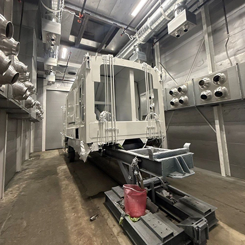
Shared spray booths regularly become production bottlenecks when multiple teams or shifts treat them simply as communal rooms rather than tightly controlled process zones. When handoffs rely on quick verbal confirmations, shops experience compounding delays, overspray migration, unrecorded filter loading, and compromised finishes.
Establishing dependable cross-shift booth operations requires treating the booth as an individual production asset with defined occupancy boundaries, rigid readiness standards, and documented handoffs.
Schedule the Full Job Cycle and Changeover
Scheduling a spray booth strictly by spray-gun trigger time creates immediate schedule slippage. True booth occupancy begins the moment the previous team clears the floor and ends only after the cabin has exhausted overspray, cleared solvent vapors, and returned to baseline operating conditions.
Total Booth Occupancy Block
- Load & Fixture Staging
- Pre-Spray Inspection & Air Blowdown
- Active Application (Trigger Time)
- Flash-Off Window
- Cure / Bake Cycle (if equipped)
- Cooldown & Air Purge
- Part Exit & Handoff Inspection
A workable schedule accounts for every stage of the cycle:
- Loading and positioning: Moving carts, hanging parts, and grounding fixtures.
- Blowdown and tacking: Removing dust from parts inside the booth before fluid flows.
- Application time: The physical spraying duration.
- Flash-off and bake: Evaporation and heated cross-linking cycles.
- Cooldown and purge cycles: Bringing part temperatures and cabin atmospheres back to ambient levels.
- Unloading and sweep: Clearing finished work and staging equipment for the next user.
Operating the exhaust fan is not an automatic green light for the next team to enter or load fresh parts. Under OSHA 29 CFR 1910.107(d)(2), mechanical ventilation must run continuously during spraying and continue for a sufficient period afterward to exhaust vapors from drying articles and finishing residues.
Because solvent chemistry, part geometry, and booth air-exchange designs vary, there is no single universal clearance interval. The incoming shift cannot assume the booth is clear simply because the fan is spinning; cycles must run their full process timer or clearance protocol before the next batch crosses the threshold.
Define Incoming-Job Readiness and Material Segregation
A spray booth should only house parts that are completely prepped, staged, and ready for liquid application. Staging unprepared work inside the cabin turns an active airflow zone into an expensive parking space and introduces dust directly into the exhaust path.
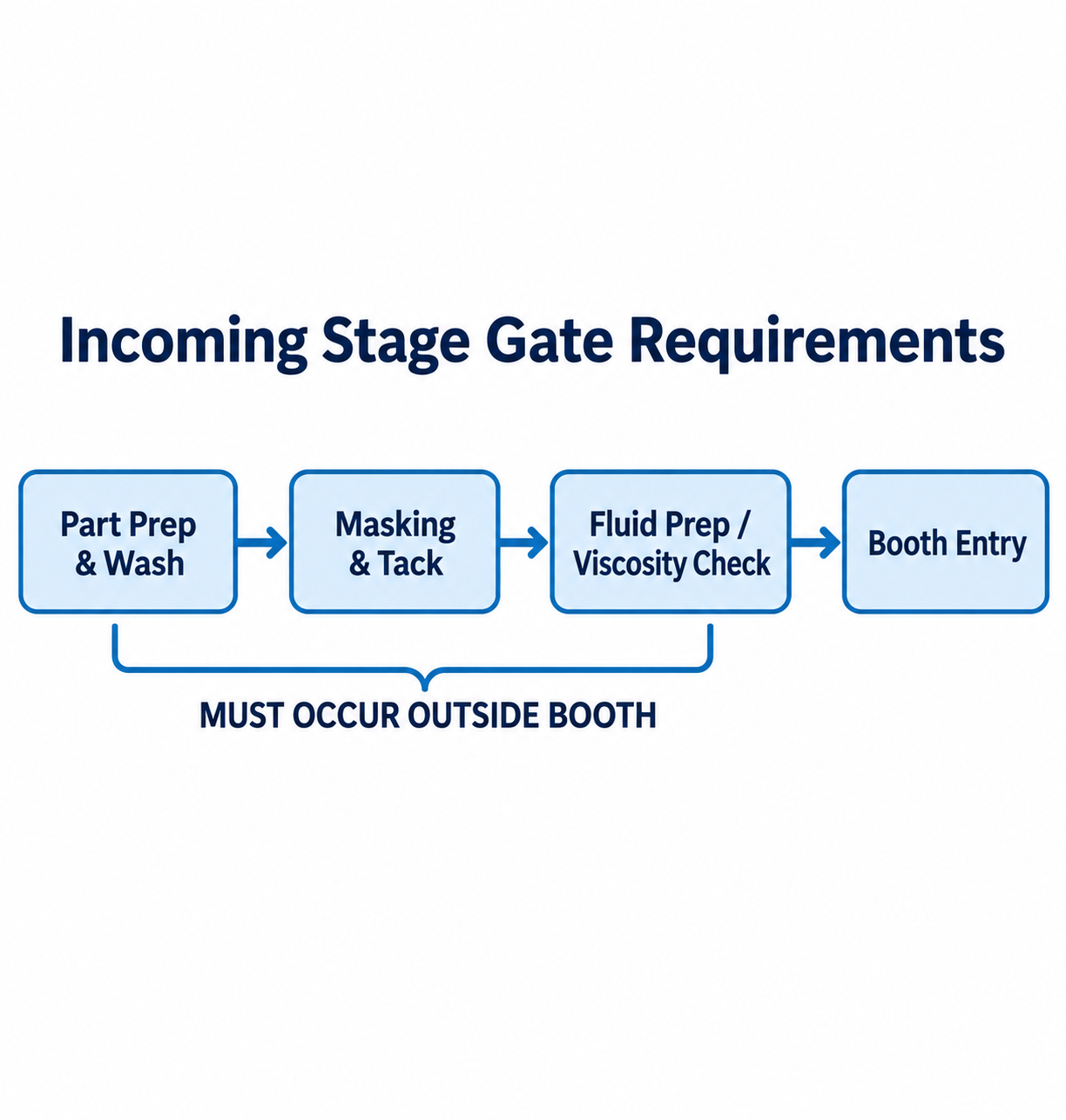
Diagram description
- Incoming Stage Gate Requirements
- Part Prep & Wash
- Masking & Tack
- Fluid Prep / Viscosity Check
- Booth Entry
- MUST OCCUR OUTSIDE BOOTH
- Part Prep & Wash → Masking & Tack
- Masking & Tack → Fluid Prep / Viscosity Check
- Fluid Prep / Viscosity Check → Booth Entry
- MUST OCCUR OUTSIDE BOOTH → Part Prep & Wash: applies outside booth
- MUST OCCUR OUTSIDE BOOTH → Masking & Tack: applies outside booth
- MUST OCCUR OUTSIDE BOOTH → Fluid Prep / Viscosity Check: applies outside booth
- Incoming Stage Gate Requirements heading.
- Part Prep & Wash → Masking & Tack → Fluid Prep / Viscosity Check → Booth Entry.
- Bracket joins ONLY first three stages, labelled MUST OCCUR OUTSIDE BOOTH; Booth Entry is outside that bracket.
Incoming operators must meet strict entry gates before taking possession of the cabin:
- Substrate readiness: Parts must be washed, thoroughly dried, masked, and wiped down in an adjacent prep station. Keep sanding and rough grinding out of the spray cycle; use designated prep areas and the facility’s approved cleaning procedures.
- Fluid verification: Coatings, catalysts, and thinners must be measured, mixed, and brought to operating viscosity in the mix room, not mixed off-the-cuff on the booth grating.
- Dedicated fluid delivery: Hoses, fluid tips, and pressure pots must be assigned to compatible coatings or cleaned under approved changeover procedures. OSHA scopes spray-nozzle and auxiliary-equipment solvent cleaning to the booth with ventilation operating; do not adopt a blanket outside-booth flushing rule.
Shift-level staging must also align with routine maintenance. Booth operators should not make ad-hoc decisions about when to swap pre-filters or service exhaust systems during a live run. Long-term filter lifecycles, burner maintenance, and duct inspections belong on a facility-wide paint booth maintenance calendar.
Daily teams follow shift-level operational checks specified in the manufacturer operating instructions to monitor intake air filters, manometer pressure drops, and electrical interlocks. If a daily threshold is crossed, the shift halts loading until the required maintenance action is cleared by the designated lead.
Record Condition, Defects, and Outstanding Maintenance at Handoff
Verbal handoffs leave the incoming shift blind to emerging equipment faults, filter saturation, and substrate contamination. A standardized handoff record pinned at the booth entrance forces accountability between outgoing and incoming personnel.
| Log Component | Required Detail | Operational Purpose |
|---|---|---|
| Outgoing Process State | Part IDs, coating batch numbers, exact stage (e.g., flash complete, cool-down active). | Prevents premature booth entry or opening doors during solvent flash. |
| Airflow Indicators | Manometer / differential pressure gauge reading (in. w.g.). | Identifies approaching filter saturation before a mid-shift blowout. |
| Visible Defect Log | Burnt-out light tubes, torn seals, filter gaps, air drops. | Flags physical defects for maintenance before finish quality drops. |
| Cabin Cleanliness | Grate overspray buildup, floor paper status, wall coatings. | Establishes baseline housekeeping before the next crew applies material. |
| Sign-Off | Signatures from both outgoing and incoming operators. | Fixes responsibility for the physical handoff condition. |
Special attention must be paid to lighting and filtration integrity. OSHA 29 CFR 1910.107(b)(10) requires transparent lighting panels to effectively isolate the spraying area and be noncombustible and resistant to breakage. If an outgoing operator cracks a lamp panel, stop spraying and escalate the damaged isolation barrier under the manufacturer’s service and release procedures.
Similarly, maintain overspray collection filters seated in their frames without bypass gaps, following the installed equipment’s filter instructions. If an outgoing team notices face loading or displaced media, the shift cannot simply pass the issue down the line.
Cross-contamination tracking is equally critical. In shops running multiple coating types, lingering overspray dust from one formulation can cause fish-eyes, adhesion failure, or cure inhibition in another. The outgoing team must log the exact chemistries used—such as epoxies, polyurethanes, or waterbornes—so the incoming crew can verify whether cabin walls and floor coverings need prep before spraying sensitive topcoats.
Escalate Capacity or Compatibility Limits
Operational discipline can resolve scheduling friction, but it cannot fix severe physical capacity limits or dangerous chemical incompatibilities. Shop managers must recognize when handoff issues stem from operational disorganization versus hardware and facility limitations.
Chemical Incompatibility and Residue Hazards
Staggering shifts does not automatically make sharing safe if coatings react negatively inside the exhaust plenum. Under OSHA 29 CFR 1910.107(g)(6), shops are strictly prohibited from spraying combinations of coatings that can cause spontaneous combustion when their residues mix inside the booth, ductwork, or exhaust filters. For instance, alternating between nitrocellulose lacquers and oxidizing varnishes or baking enamels without complete residue removal creates an immediate fire hazard.
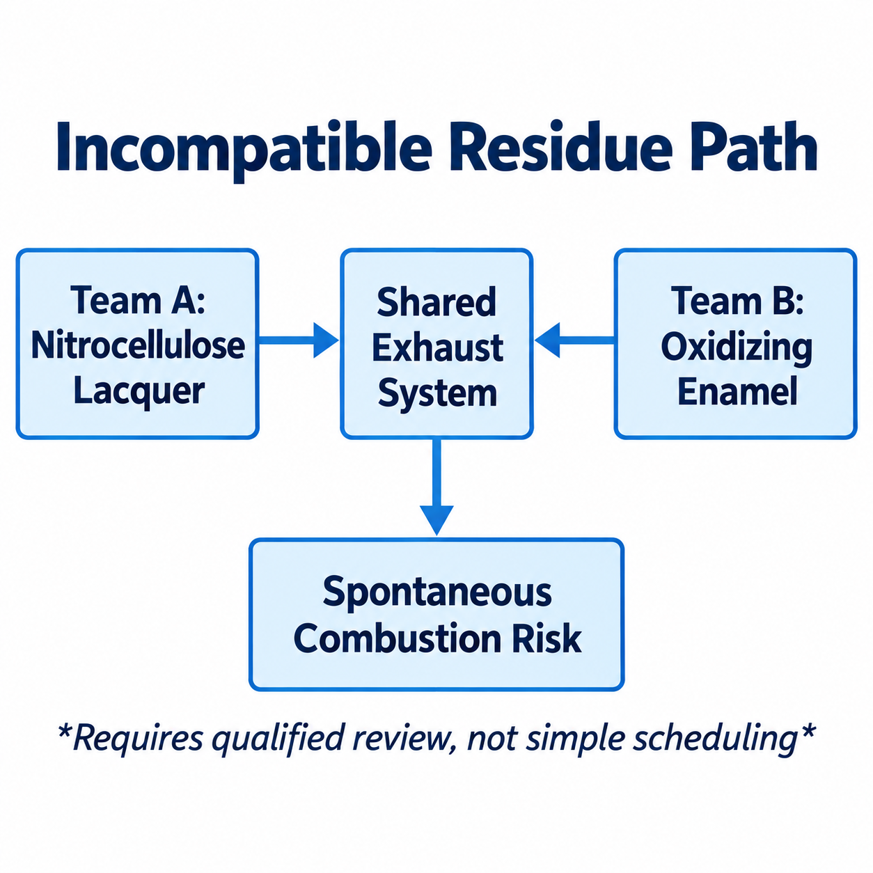
Diagram description
- Incompatible Residue Path
- Team A: Nitrocellulose Lacquer
- Shared Exhaust System
- Team B: Oxidizing Enamel
- Spontaneous Combustion Risk
- Requires qualified review, not simple scheduling
- Team A: Nitrocellulose Lacquer → Shared Exhaust System
- Team B: Oxidizing Enamel → Shared Exhaust System
- Shared Exhaust System → Spontaneous Combustion Risk
- Title Incompatible Residue Path.
- Left Team A: Nitrocellulose Lacquer points RIGHT to central Shared Exhaust System.
- Right Team B: Oxidizing Enamel points LEFT to Shared Exhaust System.
- Shared Exhaust System points down to Spontaneous Combustion Risk.
- Italic qualifier below risk: Requires qualified review, not simple scheduling.
When teams use divergent chemistries, managers cannot simply divide the schedule into day and night shifts. Handling hazardous combinations requires a qualified safety review, validated washdown protocols, or dedicated exhaust paths rather than basic schedule grouping.
Recognizing Capacity Ceilings
If a facility experiences persistent bottlenecks despite strict adherence to cycle scheduling and prep-gate discipline, the booth hardware itself may be undersized for the facility's demand. Warning signs include:
- Cure cycles continually encroaching on standard shift windows.
- Exhaust filters reaching terminal pressure drops after only a few shifts due to high solid volumes.
- Prep teams consistently idling outside while waiting on solvent clearance times.
- Cross-contamination defects continuing despite thorough dry-filtering and sweeping.
When operational adjustments no longer yield usable floor time, the solution lies in infrastructure: expanding booth footprint, adding dedicated drying and curing enclosures, or upgrading airflow capacity. To evaluate equipment additions, airflow balancing, or multi-booth configurations for high-demand facilities, contact our engineering team to review system requirements or Request a Quote.