
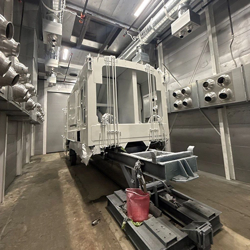
Abrasive blasting automation depends on how well the equipment accommodates incoming parts and process variation. Replacing a manual blaster with a mechanized or robotic system does not automatically increase plant throughput or lower operating overhead. In operations with high part variability, loose dimensional tolerances, or unpredictable surface contamination, automated systems often create secondary bottlenecks around fixturing, programming, and quality rework.
Evaluating an automation trial requires looking beyond raw nozzle velocity. Production managers must assess physical part presentation, compare machine architectures against handling needs, measure complete dock-to-dock cycles, and define rigorous trial standards with equipment builders.
Defining Part Repeatability and Presentation Requirements
Automated blast equipment operates on fixed paths, mechanical indexing, or pre-programmed tool vectors. Unlike a human operator who dynamically adjusts nozzle distance, angle, and dwell time when spotting a patch of stubborn scale or an off-center weld, automated blast nozzles deliver media uniformly according to their programmed parameters.
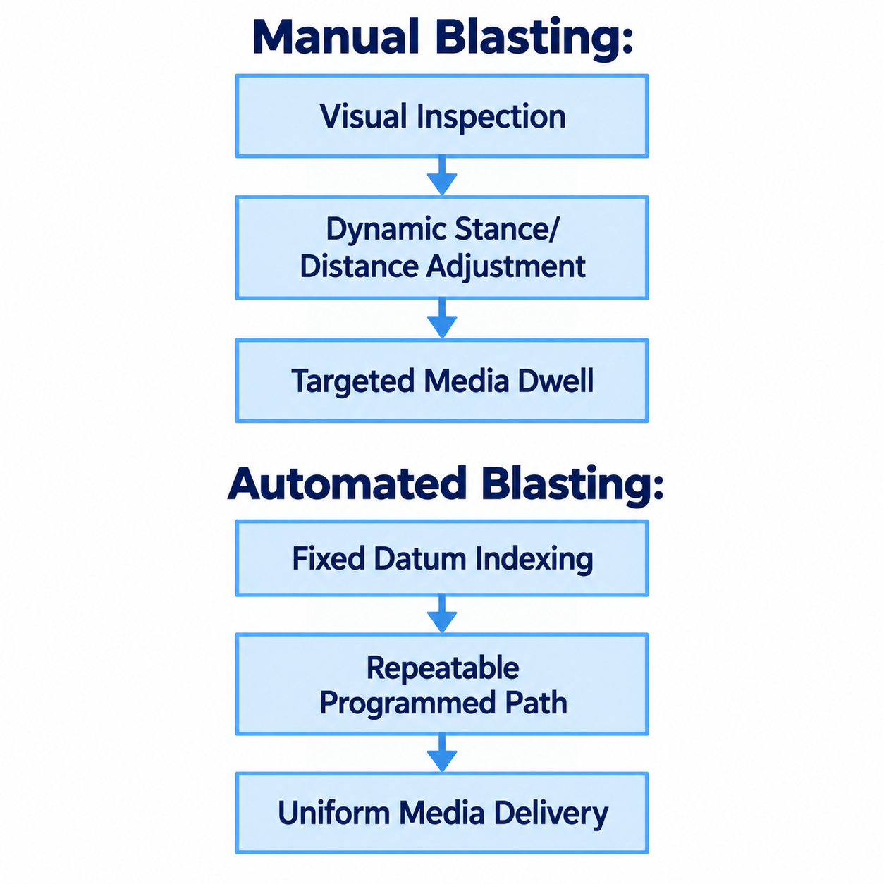
Diagram description
- Manual Blasting:
- Visual Inspection
- Dynamic Stance/Distance Adjustment
- Targeted Media Dwell
- Automated Blasting:
- Fixed Datum Indexing
- Repeatable Programmed Path
- Uniform Media Delivery
- Visual Inspection → Dynamic Stance/Distance Adjustment
- Dynamic Stance/Distance Adjustment → Targeted Media Dwell
- Fixed Datum Indexing → Repeatable Programmed Path
- Repeatable Programmed Path → Uniform Media Delivery
- Manual: Visual Inspection → Dynamic Stance/Distance Adjustment → Targeted Media Dwell
- Automated: Fixed Datum Indexing → Repeatable Programmed Path → Uniform Media Delivery
To determine if a component is viable for automation, evaluate three core baseline criteria:
- Dimensional Consistency: Castings, forgings, structural fabrications, or stampings must share consistent dimensional datums. Variation in part warping, weld bead height or flange positions can change coverage. Supplier trials should test whether the selected nozzle paths accommodate that variation.
- Surface Contamination Uniformity: Automated cycles rely on consistent incoming surface conditions. A process designed to strip light mill scale or uniform rust may need a different preparation stage for grease pockets, drawing compounds, or thick protective coatings. Review incoming contamination with the supplier; oil can contaminate reusable abrasive and interfere with separation.
- Fixturing and Part Presentation: The workpiece must be held securely in a repeatable orientation that exposes targeted surfaces to the blast stream without masking critical areas behind heavy clamping jigs. If presenting the part requires complex, multi-point manual clamping that takes longer than the blast cycle itself, automated blasting will not resolve overall cycle bottlenecks.
When reviewing industrial sandblasting booth options, operations teams must differentiate between equipment that simply encloses an operator and systems designed to process indexed workpieces. If parts cannot be presented from predictable reference points, the supplier must evaluate alternative handling or adaptive features rather than relying on booth size or recovery capacity alone.
Selecting Automation Types Across Part Profiles and Handling Methods
Automation is not a one-size-fits-all technology. Equipment configurations range from dedicated mechanical mechanisms to articulated multi-axis robots, each tailored to specific production profiles and volume demands.
| Automation Category | Best Part Profiles | Operational Trade-Offs |
|---|---|---|
| Dedicated Mechanical (Rotary, Conveyor) | Symmetrical, cylindrical, flat, or uniform geometric components | Low programming overhead; rigid fixturing; limited flex |
| Articulated Robotics | Complex, contoured fabrications with multi-axis surface profiles | High path flexibility; requires robust end-effector protection |
| Manual Enclosures | High-mix, low-volume, structural weldments with loose tolerances | High adaptability; dependent on operator fatigue and visual scan |
Dedicated Mechanical Automation
Dedicated systems use mechanical motion—such as rotary turntables, roller conveyors, tumble drums, or linear nozzle reciprocators—to pass parts through predictable blast streams.
- Application Profile: Symmetrical or high-volume uniform parts such as pipe spools, vehicle wheels, structural I-beams, flat plates, and simple shafts.
- Operating Reality: These machines are reliable workhorses for narrow part families. However, changing to a radically different component geometry may require revised fixturing, nozzle positions or handling hardware.
Articulated Multi-Axis Robotics
Robotic blast cells deploy an articulated industrial robot to manipulate either the blast nozzle around a stationary workpiece or the workpiece across a stationary nozzle bank.
- Application Profile: Complex, high-value components with varying surface planes, tight internal radii, or specific profile depth requirements across multiple faces (e.g., aerospace turbine components, suspension knuckles, and intricate structural weldments).
- Operating Reality: While robots provide path programming flexibility, abrasive blast environments are inherently destructive. Key robotic sandblasting investment considerations include the supplier’s provisions for abrasive protection, equipment wear, maintenance access and repeatable nozzle positioning.
Manual Blasting Enclosures
Retaining manual blast booths may be practical when part mix is highly varied, lot sizes are small, or incoming assemblies display wide dimensional variance. Human operators quickly adapt to mixed geometries and irregular weld splatter without needing path re-teaching or fixture re-tooling.
Automation can complement manual operations; evaluate whether non-standard repairs, rework or low-run legacy components still require a manual station.
Measuring True Cycle Throughput Beyond Blast-Nozzle Time
Equipment brochures frequently highlight arc-on or blast-on cycle time—the minutes and seconds the blast metering valve remains open. In production environments, blast-on time represents only a fraction of the total cycle. Measuring automation feasibility requires evaluating the complete dock-to-dock processing sequence:
Total Production Cycle = Tstage + Tload + Tblast + Tpurge + Tunload + Tinspect
To determine if an automated system truly improves throughput, calculate total cycle volume using realistic operational stages:
1. Staging, Masking, and Fixturing ($T_{\text{stage}}$)
Manual blasting allows an operator to steer clear of sensitive areas like grease ports, machined threads, and nameplates through line-of-sight control. Automated systems blast the entire programmed zone. This means critical features often require precision hardened steel caps, rubber plugs, or heavy masking fixtures that must be applied and removed on every run.
2. Loading and Chamber Indexing ($T_{\text{load}}$)
Manual blasting also requires part positioning and the prescribed safety and equipment checks before work begins. Automated cells require parts to be secured to precise datums, light curtains cleared, access doors interlocked, and recovery systems fully engaged before the cycle starts. Track the time required to lock fixtures and initiate the safety cycle.
3. Effective Blast-On Time ($T_{\text{blast}}$)
Automation can coordinate multiple nozzles, subject to the equipment design and the application’s required pressure. A multi-nozzle automated array can blast a surface rapidly, but only if the air compressor infrastructure supplies the required cubic feet per minute (CFM) at steady blast pressure without dropping below specified thresholds.
4. Media Blow-Off and Abrasive Clearing ($T_{\text{purge}}$)
Automated blast streams flood internal cavities, blind pockets, and horizontal ledges with spent abrasive. If the machine lacks an automated tilt table or targeted air-blow-off cycle, the supplier must identify a safe, suitable clearing stage before downstream movement.
5. Part Changeover Frequency
When a line runs one part profile continuously across an entire shift, changeover time approaches zero. When a facility processes three or four different part profiles per shift, changeover time—including loading new robot path files, swapping fixturing nests, and repositioning nozzle stands—must be factored directly into daily throughput calculations.
6. First-Pass Acceptance Yield
Throughput is accepted parts per shift, not blasted parts per shift. If an automated system blasts a part in five minutes but leaves shadowed zones behind gussets that require manual touch-up blasting, the automated cell functions merely as a pre-blast stage, adding handling steps rather than eliminating them.
Structuring Supplier Trials and Acceptance Criteria
Do not purchase or lease an automated blast cell based on computer-aided cycle simulations or generic test coupons. The operational viability of abrasive blast automation must be proven through controlled trials using your production parts under worst-case operational conditions.
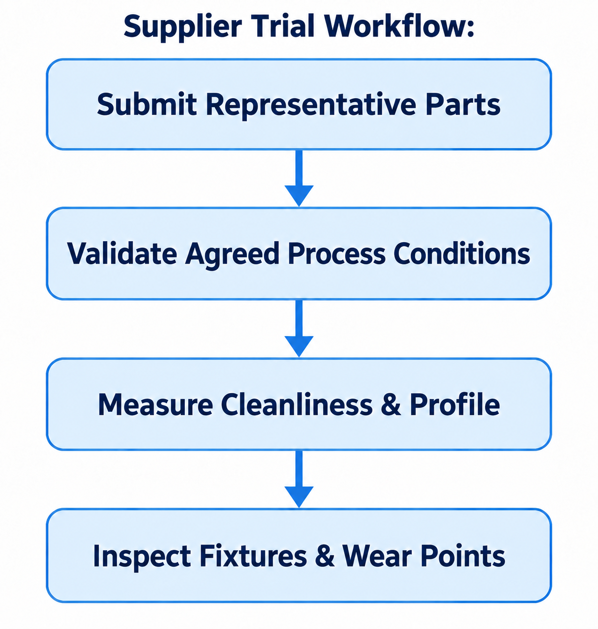
Diagram description
- Supplier Trial Workflow:
- Submit Representative Parts
- Validate Agreed Process Conditions
- Measure Cleanliness & Profile
- Inspect Fixtures & Wear Points
- Submit Representative Parts → Validate Agreed Process Conditions
- Validate Agreed Process Conditions → Measure Cleanliness & Profile
- Measure Cleanliness & Profile → Inspect Fixtures & Wear Points
- Supplier Trial Workflow: Submit Representative Parts → Validate Agreed Process Conditions → Measure Cleanliness & Profile → Inspect Fixtures & Wear Points.
When structuring an automation trial with an equipment manufacturer, define test protocols using the following framework:
Part Selection for Proof-of-Concept Trials
- Send Worst-Case Parts: Provide samples with the heaviest rust, thickest scale, and widest manufacturing tolerances seen on your shop floor. A trial run on pristine, flat sample coupons may not reveal how the system handles real production variations.
- Review Pre-Washed and As-Received Conditions: Provide the supplier with information on production oil or coolant residues and agree on required precleaning before any blast trial.
Process Performance Verification
- Verify True Air and Media Consumption: Ensure the supplier runs the trial at the exact nozzle size, operating pressure (PSI), and volumetric flow rate (CFM) planned for your facility. Measure media degradation rates and dust generation during continuous blasting.
- Specify Precise Acceptance Standards: Agree on the applicable surface requirements and their verification methods; use named standards where the job specifies them:
- Cleanliness grade (e.g., SSPC-SP 10 / NACE No. 2 Near-White Metal).
- Surface profile depth and measurement method specified for the intended coating or application.
- Edge radius or deburring tolerances on machined interfaces.
- Inspect Critical Masking Lines: Verify that blast media does not penetrate masked threads or bore diameters, and confirm that masking plugs release cleanly without excessive manual force after exposure to the blast stream.
Mechanical and Maintenance Assessment
- Fixture Wear Rate: Inspect test fixturing after multiple runs. Are locating pins and clamps showing premature wear or binding from abrasive grit ingestion?
- Maintenance Clearance: Assess the practical ergonomics of the machine. Can technicians access nozzle assemblies, reclaim ductwork, pressure vessels, and filtration units without disassembling structural members of the blast chamber?
When compiling your process parameters to request a blast booth quote, provide suppliers with a comprehensive specification sheet that details part weight ranges, maximum dimensional envelopes, incoming surface conditions, target profile depths, hourly part volume requirements, and available compressed air capacity.
Supplying rigorous baseline data enables equipment builders to configure nozzle arrays, reclaim systems, and part-handling mechanisms that match your operational reality, and helps you assess how trial results will translate to your plant floor.