
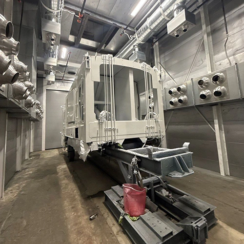
Evaluate robotic blasting from actual part presentation, accepted throughput, integration, and costs. Stable repeat work may strengthen the case, while sensing, fixturing, or adaptive control may address some variation. A robot alone does not resolve recovery, air-supply, or upstream constraints.
For operations leaders evaluating automation, the decision hinges on total cell integration and realistic operating discipline rather than the false promise of unmanned, 24/7 output.
Evaluating Process Repeatability and Part Geometry
The cell must accommodate actual geometry, orientation, and surface variation. Programmed paths, fixtures, sensors, or adaptive control may provide different capabilities; qualify the chosen system on representative parts.
| Process | Variation and Work to Assess |
|---|---|
| Manual | Operator capability, qualified technique, handling, and inspection |
| Automated | Presentation, programmed/adaptive control, handling, validation, and service |
To determine whether your components suit automation, audit your production mix across four specific manufacturing parameters:
- Part Family Envelope and Reach: Group components by size and access requirements. An articulated arm mounted on a linear track can cover wide structural elements, but deep internal pockets, complex pipe manifolds, or shadowed cavities often require auxiliary rotational axes or specialized lance nozzles. If an operator must routinely enter the cell to blast blind spots by hand, the automation investment case collapses quickly.
- Upstream Geometric Consistency: Evaluate part variation prior to surface preparation. Castings, forgings, precision-machined components, and laser-cut weldments exhibit the dimensional stability needed for automated blast recipes. Conversely, structural weldments with significant thermal distortion, variable flame-cut edges, or heavy manual tack welds force programmers to widen blast patterns, raising abrasive consumption and cycle times to ensure complete coverage.
- Lot Sizes and Changeover Penalties: High-mix, low-volume job shop work generates substantial engineering friction. Developing, testing, and touching up robot paths for small batches consumes hours of programmer and booth time. Automation yields its highest returns on medium-to-high batch volumes where fixture setups remain static for entire shifts.
- Surface Acceptance Criteria: Specify cleanliness, profile, retained features, and inspection methods. Automation can improve repeatability, but constant motion or distance does not guarantee acceptable coverage or a tight profile on every geometry.
Automation is never just a robot arm mounted inside an existing blast cabinet. It is a synchronized manufacturing process where upstream dimensional stability directly dictates downstream surface quality.
Defining the Complete Blast Cell Scope
Include the complete cell and site scope in capital comparison. The arm’s share varies with enclosure, handling, integration, controls, and support; there is no universal 20–35% split.
Complete Capital Scope
- Enclosure, blast equipment, recovery, and dust control
- Robot, environmental protection, and positioning
- Fixtures, handling, integration, and programming
- Safeguarding, controls, installation, commissioning, and support
A complete blast cell scope incorporates several interconnected subsystems:
Environmental Armoring and Blast Cabinets
Specify robot protection, environmental resistance, enclosure wear protection, and service access for the actual cell. Protective jackets, purge systems, or liners may be options, not universal requirements for every automated arrangement.
Engineering the enclosure around the blast envelope requires rigorous planning; referencing Clemco’s blast-room system guidance helps align physical booth dimensions, drive-through or batch access, and service clearance with industrial handling equipment.
Material Handling and Part Positioning
Static parts force the robot to execute wide, inefficient movements. Integrating a programmable external axis—such as a synchronized rotary turntable, a tilt-rotate trunnion, or an overhead monorail indexer—keeps the blast stream working at optimal impingement angles. Fixtures must locate parts within tight tolerances while resisting severe abrasive erosion, all without masking critical surfaces that require surface preparation.
Blast Generation and Media Management
Select compatible blast-generation and metering equipment for the required duty and control. Automation does not universally require one continuous-duty pressure-vessel configuration.
Confirm media transport, separation, collection, and delivery compatibility across the cell. Clemco’s automated blasting solutions illustrates application-specific integration; a floor conveyor, bucket elevator, and air-wash separator are not compulsory in every design.
Safety Safeguarding and Controls
A qualified integrator must define safeguarding and required safety functions from the actual risk assessment, equipment, and applicable requirements. Verify access, emergency stops, hazardous energy, fault recovery, and authorized restart; do not prescribe instantaneous vessel dumping or one universal interlock/scanner package.
Labor Distribution, Throughput, and Realistic Utilization
A frequent planning mistake is assuming a robotic blast cell operates continuously without human involvement. While automation removes the operator from the grueling, high-hazard environment inside the booth, human labor shifts from holding the nozzle to managing the cell.
| Work Content | Measure in the Actual Project |
|---|---|
| Handling / Fixturing | Load, clamp, changeover, unload |
| Programming / Operation | Setup, monitoring, authorized correction |
| Quality | Inspection, acceptance, touch-up, rework |
| Maintenance | Wear, replenishment, fault recovery, and service |
The Myth of 24/7 Unattended Operation
Plan for loading, inspection, wear, replenishment, faults, and service. Claims of unattended multi-shift performance need system-specific evidence and a defined intervention/support scope.
Use measured or demonstrably supported availability, performance, quality, and utilization assumptions. OEE and mechanical utilization are different metrics; neither has a universal 65–75% target for blast cells. Account for:
- Loading, clamping, and unloading heavy workpieces.
- Checking nozzle throat erosion with a nozzle gauge (a worn venturi nozzle increases CFM demand and degrades blast velocity).
- Replenishing abrasive media and clearing scalping screen trash bins.
- Inspecting robot protective sleeves, positive-pressure purge pressures, and rubber wall curtains.
- Clearing occasional part-locating or proximity sensor faults caused by dust accumulation.
Labor Reallocation and Safety Obligations
Measure labor per accepted part across programming, handling, inspection, operation, and maintenance. Automation may shift tasks and skill requirements without guaranteeing a particular labor reduction.
Automation significantly reduces musculoskeletal strain, heat stress, and direct operator exposure to high-pressure blast streams. However, it does not eliminate dust control or air quality responsibilities. The dust hazards generated within the enclosure depend on both the abrasive selected (e.g., steel grit, garnet, aluminum oxide) and the coating being removed (such as lead-based primers, zinc silicates, or toxic epoxy systems).
Enclosure dust collection, make-up air ventilation rates, and respiratory protection standards for personnel entering the enclosure for maintenance or inspection remain distinct, mandatory safety obligations. Qualified environmental health and safety personnel must establish and govern cell ventilation rates, lockout/tagout (LOTO) procedures for pressurized vessels and robotic axes, and waste-stream disposal protocols.
The Financial Model: Calculating Real-World ROI
To determine if an automated blast project is justified, run a comparative business case that pits current manual blasting operations against the full lifecycle costs of an integrated cell.
Simple payback is calculated directly:
Simple Payback (Years) = (Total Incremental Investment) / (Annual Net Benefit)
Where Total Incremental Investment encompasses the complete capital expenditure (robot, enclosure, recovery system, integration, engineering, safety fencing, and foundation prep), and Annual Net Benefit represents the net operating savings realized each year.
The following is a fictional calculation example, not supplier pricing or measured performance. It assumes 4,000 scheduled hours/year and the labor, media, rework, and maintenance values shown. Replace them with pilot data and quotations; include unmodeled energy, support, downtime, and other project costs before using the business case.
Base Case Operational Comparison
| Parameter / Cost Driver | Manual Baseline (2 Booths, 2 Operators/Shift) | Automated Cell (1 Robot Cell, 1 Operator/Shift) | Operational Impact & Notes |
|---|---|---|---|
| Direct Blast Labor | 8,000 labor-hours/year @ $32.00/hr loaded ($256,000) | 4,000 labor-hours/year @ $38.00/hr loaded ($152,000) | Cell operator commands higher technical pay; 50% net labor-hour reduction. |
| Assumed Rework / Touch-up | 8.5% ($42,000/year) | 1.5% ($7,500/year) | Fictional inputs to validate; automation does not eliminate process variability. |
| Assumed Abrasive Usage | 120 tons/year ($108,000) | 85 tons/year ($76,500) | Fictional consumption/cost inputs to replace with accepted-output trial data. |
| Nozzles, Hoses & Wear Parts | $14,000 / year | $22,000 / year | Higher consumable cost due to specialty robotic nozzles, jacket replacements, and seal kits. |
| Cell Maintenance Labor | $8,000 / year (Basic mechanical upkeep) | $24,000 / year (Electromechanical & robotic PMs) | Specialized preventative maintenance routines require skilled industrial maintenance time. |
| Annual Cost of Listed Assumptions | $428,000 | $282,000 | Difference: $146,000/year before unmodeled costs |
Capital Investment and Payback Model
| Fictional Capital Assumption | Amount |
|---|---|
| Hardware & Enclosure | $380,000 |
| Robot, Protection & Turntable | $160,000 |
| Integration, Engineering & Programming | $110,000 |
| Freight, Installation & Site Prep | $45,000 |
| Initial Parts, Tooling & Commissioning | $30,000 |
| Total | $725,000 |
These are demonstration inputs, not price benchmarks.
- Gross Annual Operating Savings: $146,000
- Less Ramp-up Efficiency Loss (Year 1 only, modeled at 15%): -$21,900
- Stabilized Annual Net Benefit: $146,000 / year
- Illustrative Stabilized Simple Payback: $725,000 ÷ $146,000 ≈ 4.97 years, using only the stated assumptions.
This illustration yields about five years before unmodeled costs or a full cash-flow analysis. Additional accepted throughput has value only where demand, downstream capacity, margin, and actual cell performance support it.
The sensitivity analysis below illustrates how changes in part volume throughput and labor savings shift the economic balance:
Payback Sensitivity to Utilization and Production Volume
| Operational Scenario | Annual Net Benefit | Adjusted Capital Outlay | Calculated Simple Payback |
|---|---|---|---|
| Assumed Lower-Utilization Case | $68,000 | $680,000 | 10.0 Years |
| Base Case Assumptions | $146,000 | $725,000 | 4.97 Years |
| Assumed Higher Accepted Volume | $235,000 | $725,000 | 3.09 Years |
| Assumed Higher-Duty Case | $340,000 | $760,000 | 2.24 Years |
Test the sensitivity to handling, loading, changeovers, faults, demand, and accepted throughput. A short payback cannot be inferred from shift count or the robot’s motion-cycle time alone.
Designing the Pilot and Factory Acceptance Test
Never commit full capital expenditure to an automated blasting integration based solely on a computer-generated reach study or cycle-time simulation. The physical behavior of high-velocity abrasive, dust cloud opacity, and part distortion can disrupt theoretical models.
Structure a rigorous two-stage acceptance testing protocol before the cell ships to your facility:
Acceptance Pipeline
- Representative proof-of-concept parts and acceptance criteria
- Qualified factory tests of process and safety functions
- Site commissioning with actual utilities, handling, media, and production conditions
1. Proof-of-Concept Blasting Trials
Send physical test parts to the robot integrator or equipment manufacturer's development laboratory. Ensure these represent real-world shop parts, not "golden samples" with ideal geometries.
Verify the following process parameters under live blasting:
- Optimal nozzle standoff distance and angle of impingement for the target coating or scale.
- Abrasive consumption per square foot blasted.
- Surface profile uniformity across weld seams, internal corners, and flat plates.
- Cycle time validation against the theoretical motion model.
2. Factory Acceptance Testing (FAT) at the Integrator
Have the qualified integrator define representative factory acceptance tests and safe fault simulations for the actual cell:
- Worst Credible Variation Testing: Present parts that represent the outer boundaries of upstream tolerances—maximum allowable thermal warpage, heavy weld spatter, and thickest expected mill scale. Verify that the robot's motion program covers these variations without requiring manual touch-up.
- Fault Recovery Verification: Qualified personnel verify safeguarding, emergency response, isolation, and authorized restart under the approved test procedure. Do not defeat controls or assume automatic resumption without required checks or resets.
- Sensor and Air-Purge Integrity: Confirm that robot protective jackets maintain positive air pressure during live operation and that optical or proximity sensors remain functional in high-dust environments.
3. Site Acceptance Testing (SAT) on the Shop Floor
After installation, use agreed representative production trials to verify:
- Cleanliness meets the agreed visual standard (e.g., SSPC-SP 10).
- Specified profile and coverage at the inspection locations and sampling plan agreed for the actual job.
- Part-to-part cycle time repeatability meets or exceeds the baseline operational model.
- Dust collector differential pressure stabilizes within the manufacturer's designated operating window.
Sign off on final integration milestones only after the system proves its capability under real production conditions on your shop floor.
Moving from Business Case to Equipment Specification
Base the automation decision on accepted trial results, flow, safety, service, capital, and operating costs. Steady repeat work can suit automation, but reliable quality, reduced rework, or economic return must be demonstrated for the actual project.
Before finalizing cell architecture, operational teams must resolve specific equipment requirements around the blast perimeter. Explore strategic approaches to reducing abrasive waste to ensure your operating media budget remains balanced over multi-shift production runs.
If your facility is managing a diverse mix of large structural weldments alongside high-volume parts, evaluate conventional sandblasting booth options to determine whether a hybrid configuration—pairing a standard manual booth with an automated work cell—better suits your capital strategy.
When you are ready to evaluate floor footprints, enclosure requirements, and recovery integration against your plant's incoming drawings and utility parameters, reach out to an application specialist to request a sandblasting booth quote. Present your part envelopes, cycle time goals, compressed air capacity, and shift schedules to verify that the equipment configuration matches your capital business case.