
A uniform blast finish is not simply an even shade of gray across a part. True repeatability requires separating visual cleanliness, anchor profile depth, and surface appearance into distinct, measurable criteria. When operators treat these properties as interchangeable, batches fail adhesion tests, consume excess coating, or develop premature corrosion despite appearing acceptable under shop lighting.
Achieving consistent results across production runs demands an established qualification process, disciplined coverage habits, and systematic inspection tailored to the specific coating specification.
Differentiating Cleanliness, Profile, and Visual Appearance
Visual appearance can mask serious surface preparation defects. A part blasted with worn, rounded media may display a uniform, matte finish while failing to produce the angular anchor pattern required for mechanical adhesion. Conversely, an aggressively pitted surface might meet roughness depth requirements while harboring embedded mill scale or salt deposits within its valleys.
Coating systems require specific, quantified criteria rather than general smoothness. For example, the Jotun Jotacote F60 application guide demonstrates that coating specifications govern cleanliness standards, profile depth, surface contamination, and ambient environmental limits as independent acceptance factors. This guide explicitly mandates pre-blast degreasing and post-blast inspections for dust, soluble salts, and surface moisture. The exact numerical tolerances for these factors vary by coating formulation, dry film thickness (DFT), and service environment; applying a single generic blast standard across different primers can miss their specific preparation requirements.
Acceptance criteria must isolate three elements:
- Surface Cleanliness: The removal of oil, grease, mill scale, rust, old coatings, and chemical salts, assessed against defined visual standards (such as SSPC/NACE or ISO pictorial grades) and non-visual chemical tests.
- Surface Profile: The peak-to-valley height and texture (angular grit pattern versus rounded shot peen) necessary to anchor the specific coating system without protruding through the primer.
- Visual Uniformity: The consistent distribution of blast coverage across weld seams, flat panels, and structural transitions, helping identify skipped or under-blasted areas for closer inspection.
Qualifying the Abrasive and Process on Representative Parts
Handbooks do not provide universal blast settings. Blast pressure, nozzle standoff distance, angle of impingement, and abrasive selection must be qualified on actual production parts or representative coupons that match the alloy, hardness, and initial surface condition of the job.
Starting substrate conditions dictate media behavior. Hot-rolled carbon steel covered in tight mill scale behaves differently under impact than pitted steel or light-gauge aluminum. Angular grit cuts and fractures brittle scale to generate an anchor profile, whereas spherical shot compresses the surface, peens defects, and leaves a rounded valley structure. Using shot where a sharp, angular anchor is specified can leave a nonconforming profile, regardless of how uniform the blasted part looks.
When establishing qualified trial parameters, operators must account for the whole preparation sequence. In many shops, this means combining blasting with other surface treatments such as specified cleaning or chemical pretreatment. Remove oil and grease by the coating manufacturer’s approved cleaning method before blasting; blasting contaminated surfaces can spread contamination to the prepared surface and recovered abrasive.
Document the qualified trial variables as a locked procedure:
- Abrasive type, size distribution, and hardness
- Nozzle type, orifice size, and dynamic pressure at the nozzle, verified by trained personnel using approved measurement procedures
- Target standoff distance and angle of attack established during the qualified trial
- Required pass speed and dwell times for specific geometries
Establishing Repeatable Part Presentation and Operator Coverage
Manual blast variation usually comes down to physical fatigue, poor part access, and inconsistent pass mechanics. When an operator must stretch across a large weldment or bend double to reach lower flanges, nozzle distance increases, the blast angle flattens, and surface profile drops significantly.
Standardized coverage requires a repeatable routine for presenting parts to the operator:
- Racking and Positioning: Stage components at a comfortable working height. If an operator cannot maintain the qualified standoff distance across the entire face of the component, use rotators, turntables, or adjustable fixtures to bring the work into their primary blast zone.
- Systematic Stroke Overlap: Work the nozzle in a consistent pattern across flat expanses, using the overlap established during process qualification. Sweeping in random arcs creates alternating stripes of heavy profile and under-blasted shadow areas.
- Targeting Difficult Geometries: Internal corners, blind pockets, stiffener gussets, and cut edges require dedicated dwell strategies. Address these complex features first with a deliberate, direct attack angle before finishing adjacent broad surfaces.
- Managing Media Consistency: Recirculated systems experience gradual shifts in blast media condition as particles shatter into fines and dust collectors extract waste. If the working mix is not replenished systematically, the shift in particle size alters blast velocity, cutting speed, and the resulting anchor pattern across the shift.
Inspecting the First Piece and High-Variation Zones
Never wait until an entire lot is finished to verify surface quality. Check the first production piece immediately after blasting, and focus measurement tools on the zones most vulnerable to coverage breakdown.
Surface profile requires the assessment method specified for the job. The Elcometer Understanding Surface Profile explanation defines profile as peak-to-valley height and relates the required profile to the coating specification; visual cleanliness is a separate acceptance check. Depending on the coating specification, operators must use replica tape measured with a calibrated spring micrometer, surface profile needle gauges, or surface roughness comparators. Eyeballing the surface or using fingernail scratch tests does not meet modern coating requirements.
Direct inspection toward areas where operator mechanics are most prone to drift:
- Recessed Fillets and Welds: Check the root of inside corners where abrasive bounce-back reduces impact energy and leaves mill scale intact.
- Edges and Corners: Profile often spikes on outside radii where the blast pattern concentrates, or drops where the nozzle passes too quickly over the boundary.
- Extreme Reach Points: Inspect the highest, lowest, and furthest edges of the part, where operators tend to over-extend standoff distance, resulting in lower impact velocity and inadequate profile depth.
- Contaminant Traps: Test low-lying pockets for abrasive dust accumulation, which prevents paint from contacting the profile valleys.
Diagnosing Process Drift and Requalifying Changes
When profile depth or cleanliness drifts outside acceptance limits midway through a batch, halt production to isolate the cause. Uncontrolled drift typically tracks back to air delivery issues, abrasive degradation, or mechanical component wear.
Equipment inspection should proceed methodically. The Clemco Classic Blast Machine OM 22501 manual identifies several critical operational wear areas to observe during troubleshooting, including nozzle orifice enlargement, worn metering valve components, remote control line leaks, and moisture buildup within the separator. A nozzle worn by just one or two sizes demands significantly more CFM from the compressor; if the air compressor cannot supply the increased volume, nozzle pressure drops, particle velocity plummets, and the resulting profile can change.
In recycling systems, inspect the operating abrasive blend directly. The Winoa WA-MO operating-mix inspection standard outlines procedures for representative sampling and sieve analysis of steel abrasive mixes. In a functioning reclaim system, fresh coarse abrasive blends with rounded working particles and a controlled fraction of fines. If the air-wash separator fails or dust collection exhaust rates shift, the operating mix can shift away from its qualified size distribution, changing cleaning performance and the resulting finish.
If inspection reveals an equipment problem, worn consumable, or contaminated air supply:
- Identify and document the physical root cause (e.g., choked moisture trap, worn nozzle, depleted abrasive hopper).
- Correct the mechanical issue using approved procedures.
- Verify line pressure at the nozzle under dynamic load.
- Blast and measure a test piece using the qualified baseline parameters.
- Requalify the process before releasing the rest of the production run.
Aligning Equipment and Process Control
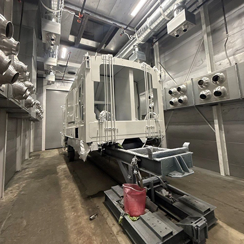
Consistent surface preparation requires matching production demands with the right facility capabilities. PaintBooth provides specialized sandblasting booth equipment, blast rooms, dust recovery systems, and ventilation units configured to help operations maintain steady air volume, clear visibility, and reliable media reclamation across demanding production schedules.
To review equipment options or discuss how a purpose-built blasting enclosure can support your coating specifications and surface preparation standards, contact PaintBooth to evaluate your production requirements.