
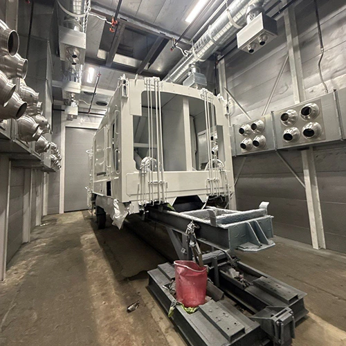
Setting up an industrial abrasive blast booth involves two distinct timelines: off-site equipment fabrication and on-site facility preparation. Physical assembly is only one part of the total project duration; engineering submittals, any concrete work, utility infrastructure, and permitting also affect the schedule.
A successful installation depends on running these tracks in parallel. Treating site readiness as an afterthought can cause delivery delays, staging bottlenecks, and prolonged downtime.
Separate Equipment Delivery from Site Readiness
Equipment fabrication lead time rarely matches the time required to prepare your facility. Manufacturing an industrial blast room—enclosure panels, abrasive recovery machinery, dust collection, and pressure vessels—depends on supplier backlog and engineering complexity. Site preparation, however, must be scheduled around your active operations, local permitting bodies, and subcontractor availability.
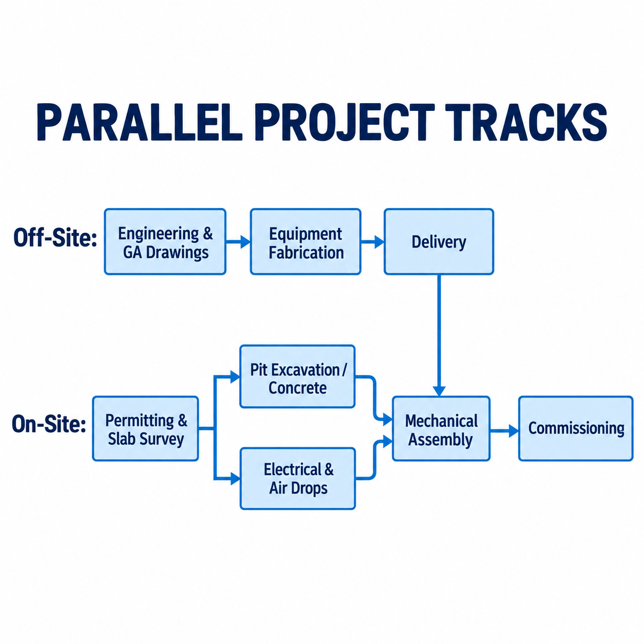
Diagram description
- PARALLEL PROJECT TRACKS
- Off-Site:
- Engineering & GA Drawings
- Equipment Fabrication
- Delivery
- On-Site:
- Permitting & Slab Survey
- Pit Excavation / Concrete
- Mechanical Assembly
- Commissioning
- Electrical & Air Drops
- Engineering & GA Drawings → Equipment Fabrication
- Equipment Fabrication → Delivery
- Permitting & Slab Survey → Pit Excavation / Concrete
- Permitting & Slab Survey → Electrical & Air Drops
- Pit Excavation / Concrete → Mechanical Assembly
- Electrical & Air Drops → Mechanical Assembly
- Delivery → Mechanical Assembly
- Mechanical Assembly → Commissioning
- Title PARALLEL PROJECT TRACKS.
- Off-Site: Engineering & GA Drawings → Equipment Fabrication → Delivery.
- On-Site: Permitting & Slab Survey branches to Pit Excavation / Concrete and Electrical & Air Drops.
- Both branches converge into Mechanical Assembly.
- Delivery also feeds Mechanical Assembly from above.
- Mechanical Assembly → Commissioning.
Evaluating different sandblasting booth options early dictates your site preparation schedule. A complete blast room system integrates three primary subsystems, each with distinct site impacts:
- Enclosure and Material Handling: Modularity speeds up wall assembly, but room size, overhead crane slots, rail tracks, or drive-through roll-up doors alter floor loading and clearance requirements.
- Abrasive Recovery Systems: Pneumatic floor recovery systems circulate light media using high-velocity air streams, demanding less foundation modification. In contrast, mechanical recovery systems (screw conveyors, belt bucket elevators, and floor hoppers) excel with heavy, aggressive media like steel grit, but they often require deep concrete pits or elevated ramps.
- Air Filtration and Dust Collection: Dust collectors need the electrical, cleaning-air, and duct connections specified for the selected design; wall or roof penetrations may add structural and environmental reviews.
If your plant chooses an above-ground room with an external ramp to avoid floor cutting, excavation may be reduced. If you specify a flush-floor design with full-floor mechanical reclamation, excavation and concrete curing may control your schedule critical path.
Confirm Drawings, Foundations, and Utility Coordination
On-site progress stops immediately if the equipment lands on an unverified foundation. Before steel is cut or concrete is poured, secure the supplier's General Arrangement (GA) drawings and foundation plans. These documents establish the dimensional tolerances, static and dynamic anchor loads, and utility termination points your contractors need.
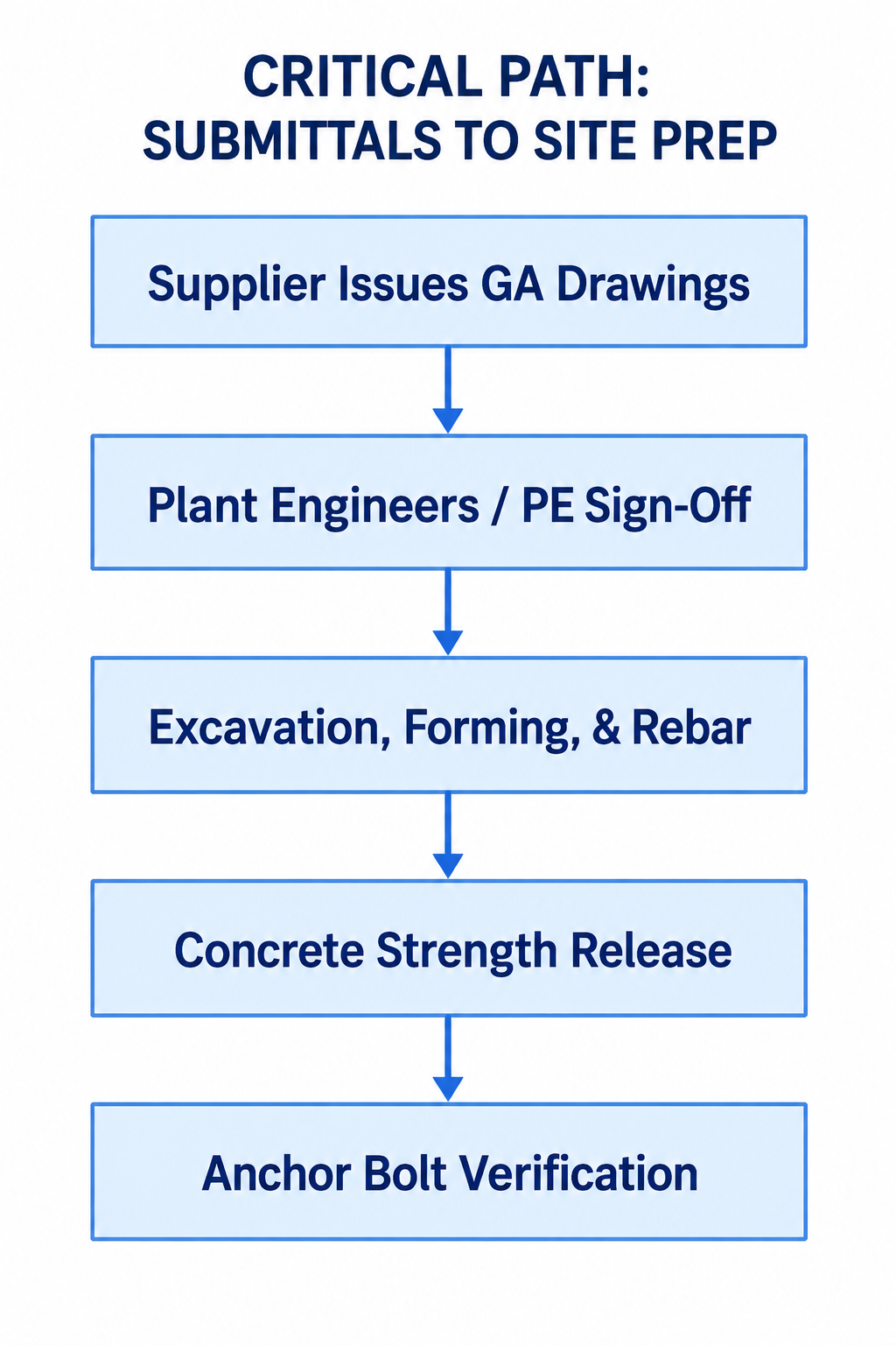
Diagram description
- CRITICAL PATH: SUBMITTALS TO SITE PREP
- Supplier Issues GA Drawings
- Plant Engineers / PE Sign-Off
- Excavation, Forming, & Rebar
- Concrete Strength Release
- Anchor Bolt Verification
- Supplier Issues GA Drawings → Plant Engineers / PE Sign-Off
- Plant Engineers / PE Sign-Off → Excavation, Forming, & Rebar
- Excavation, Forming, & Rebar → Concrete Strength Release
- Concrete Strength Release → Anchor Bolt Verification
- Title and five vertically stacked boxes in order with downward arrows: Supplier Issues GA Drawings → Plant Engineers / PE Sign-Off → Excavation, Forming, & Rebar → Concrete Strength Release → Anchor Bolt Verification.
Foundations and Excavation Realities
Civil work can cause unexpected delays. If your recovery design utilizes localized collection hoppers, foundation requirements scale directly with hopper geometry. For example, standard hopper configurations (such as 2x2-foot versus 3x3-foot arrangements) can have different floor-mounting, opening, and clearance requirements:
- Pit Depth and Water Tables: A deep elevator pit or cross-screw trench can hit sub-slab water tables, requiring specialized sealants, sump pumps, or tanking membranes.
- Concrete Curing: Concrete loading and anchor installation must follow the engineer’s strength and curing requirements for the selected mix and design.
- Anchor Bolt Templates: Misaligned anchor bolts or out-of-level slabs will stop wall-panel erection. Verify slab levelness across the entire footprint before unloading trucks.
Contractor Coordination Matrix
Preparing your site requires managing several trades simultaneously. Coordinate utility drops well ahead of delivery:
| Subcontractor / Trade | Scope of Work | Primary Timeline Dependencies |
|---|---|---|
| Civil / Concrete | Slab coring, pit excavation, rebar, pouring, and anchoring surfaces. | Cure times; soil conditions; water table depth. |
| Electrical | Electrical supply at the specified voltage and phase for dust collector fan, elevator motors, recovery augers, and room lighting. | Transformer capacity; lead times on disconnect switches and motor starters. |
| Mechanical / Piping | Clean, dry compressed air supply lines sized for blast nozzles and pulse-jet dust filters. | Pipe sizing (ID diameter); dedicated dryer/receiver tank placement. |
| Roofing / General | Ductwork penetrations for dust collector exhaust stacks and makeup air louvers. | Weather; local environmental exhaust permits; building structural modifications. |
Integrating custom sandblasting booth features—such as multi-operator blast manifolds, specialized crane cutouts, or automated work cars—increases engineering review cycles. Lock these submittals down early to avoid re-work while contractors are actively on site.
Plan Delivery, Assembly, and Commissioned Startup Milestones
Once the site is prepared and the equipment arrives, execution shifts to staging, mechanical erection, electrical tie-ins, and step-by-step commissioning. Treat each phase as a discrete gate that requires sign-off before proceeding.
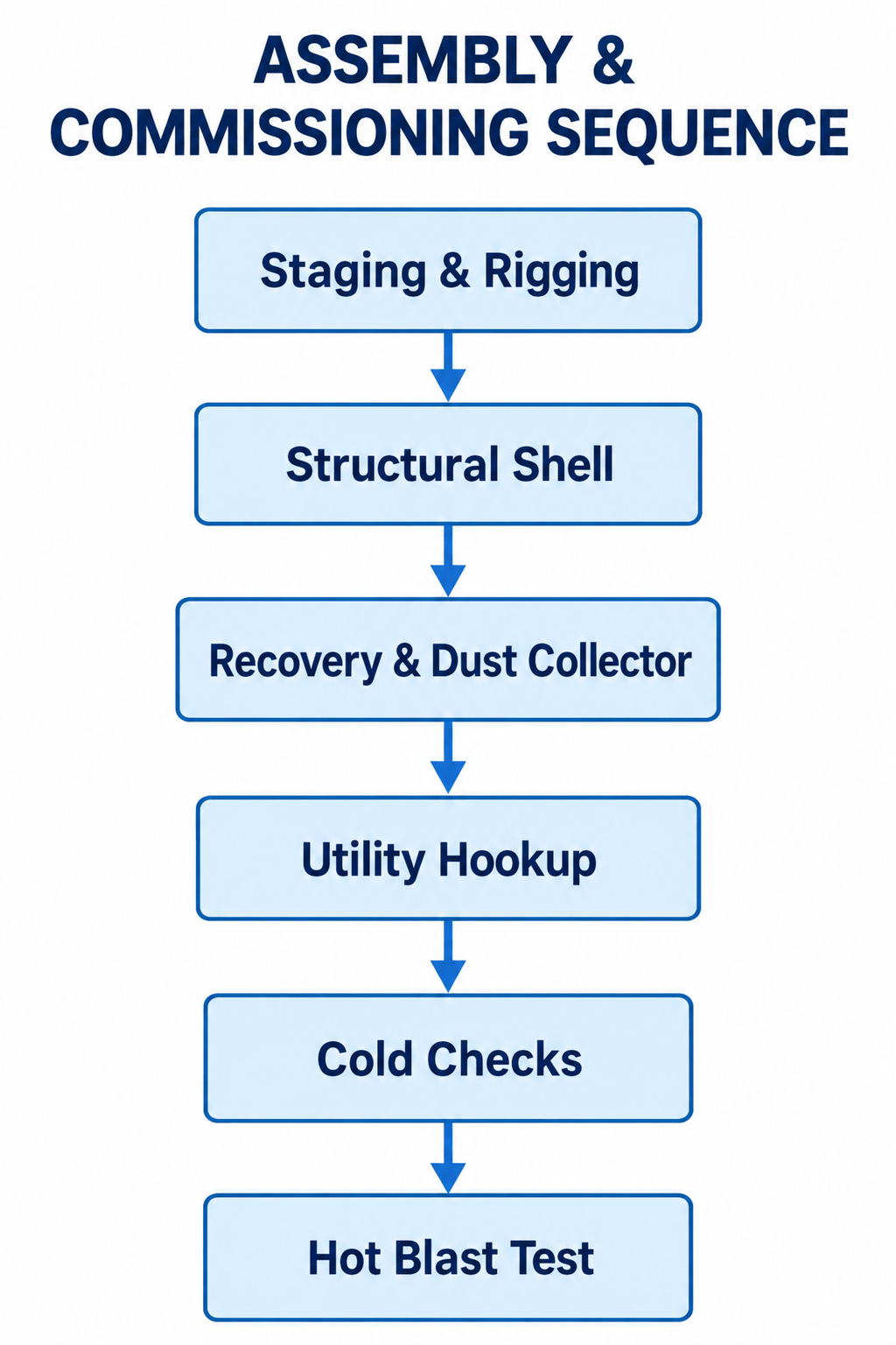
Diagram description
- ASSEMBLY & COMMISSIONING SEQUENCE
- Staging & Rigging
- Structural Shell
- Recovery & Dust Collector
- Utility Hookup
- Cold Checks
- Hot Blast Test
- Staging & Rigging → Structural Shell
- Structural Shell → Recovery & Dust Collector
- Recovery & Dust Collector → Utility Hookup
- Utility Hookup → Cold Checks
- Cold Checks → Hot Blast Test
- Staging & Rigging → Structural Shell → Recovery & Dust Collector → Utility Hookup → Cold Checks → Hot Blast Test
Offloading and Staging
A commercial blast room delivery typically arrives on multiple flatbeds or dry vans. You will need a designated laydown yard adjacent to the installation bay.
- Equipment Required: Verify forklift capacity (and crane service if erecting tall bucket elevators or heavy one-piece dust collectors).
- Clearances: Confirm door opening heights and transit corridors between your delivery dock and the installation bay.
Manage Schedule Assumptions and Changes
Unplanned delays during booth setup can stem from unverified operational assumptions. Clear boundaries of responsibility between the buyer, the equipment manufacturer, and local trades prevent schedule drift.
| Risk Factor | Mitigation Step |
|---|---|
| Air Compressor Undersizing | Audit plant air: sum all blast nozzles and specified collector air demand. |
| Out-of-Spec Concrete Floor | Survey slab with laser level during GA review phase. |
| Missing Lifting Equipment | Establish crane/rigging responsibilities inside the assembly contract. |
| Delayed Discharge Permits | Confirm local permit requirements during initial project planning. |
Compressed air infrastructure can be a schedule dependency. Confirm the combined demand of the selected nozzles, collector cleaning system, and other users against available plant capacity. Failing to account for dedicated compressor lead times can strand a finished booth for weeks.
When you prepare to request a blast booth quote, anchor the schedule conversation around explicit site dependencies rather than open-ended target dates.
Supplier Specification and Schedule Inquiry
Provide the following site parameters to your equipment supplier to receive an accurate project milestone schedule:
- Target Blast Media and Mesh Size: (e.g., #25 steel grit, 80-mesh garnet, aluminum oxide). This determines mechanical vs. pneumatic recovery sizing.
- Workpiece Dimensions and Handling: Maximum part weight, envelope size, and movement method (forklift, overhead crane slot, rail cart).
- Foundation Constraints: Available pit depth limits, slab thickness, and floor core drilling approvals.
- Available Plant Utilities: Confirmed voltage, phase, and available air volume at the specified operating pressure at the installation bay.
- Physical Footprint and Clearances: Distance from nearest wall, overhead truss clearance, and route access to outdoor dust collectors or roof exhaust points.
- Installation Scope of Work: Clarify whether you are purchasing equipment-only (with self-installation), factory-supervised assembly, or full turnkey mechanical/electrical erection.