
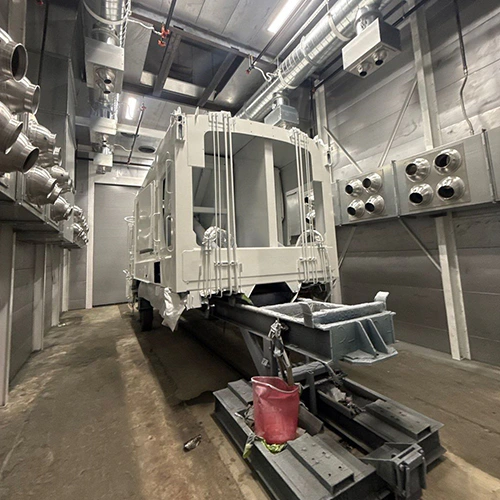
Deciding between a batch system and a continuous conveyor line is not a simple volume calculation. High part counts alone do not justify a conveyor, just as low overall tonnage does not automatically point to a batch booth and box oven.
The real decision hinges on process alignment: how substrate thickness varies across your production schedule, how often your operators switch colors, how parts are pretreated, and how an unexpected interruption at one station ripples through the rest of the facility. Choosing the wrong architecture locks your operation into permanent labor inefficiencies, inconsistent cure cycles, or chronic floor-space bottlenecks.
| OPERATIONAL FACTOR | BATCH ARCHITECTURE | CONVEYOR ARCHITECTURE |
|---|---|---|
| Part Mix & Geometry | High mix, wide gauge variance, large frame envelopes | Uniform shapes, consistent cross- sections and weights |
| Color Changes | Frequent switches between separate loads | Dedicated colors or long runs between purges |
| Process Decoupling | Stages operate independently on carts or rolling racks | Rigid mechanical link; shared-chain stops can affect multiple stages |
| Thermal Mass Profile | Cycles tailored to specific gauge loads | Line speed governed by slowest-curing part |
Map Parts, Demand, and Changeovers Across the Process
A powder coating line may include six stages: application-appropriate pretreatment, moisture dry-off where needed, powder application, cure, cool-down, and unloading. Evaluating system architecture requires mapping how your actual part catalog moves through this entire chain rather than isolating the spray booth or the cure oven.
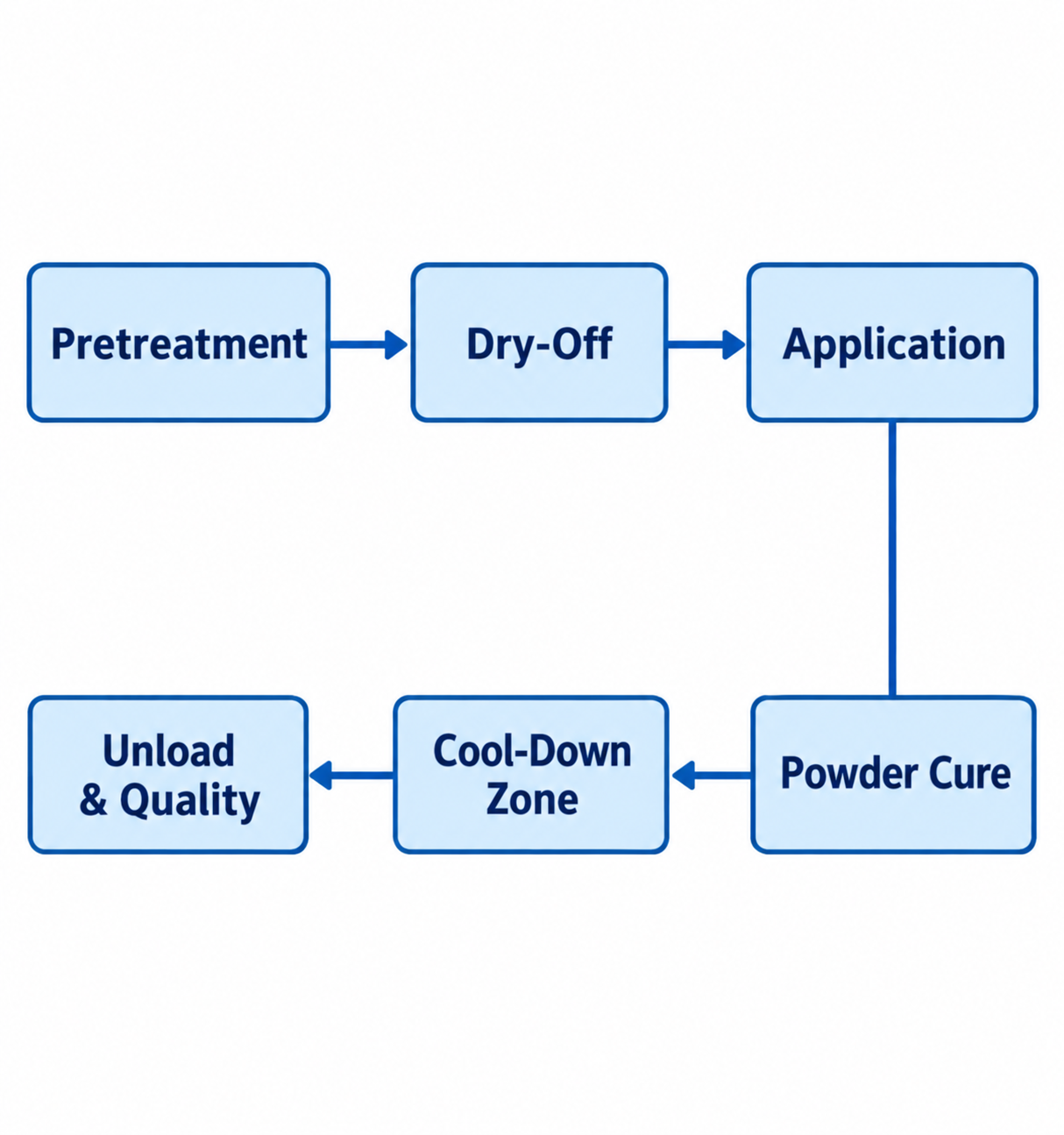
Diagram description
- Pretreatment
- Dry-Off
- Application
- Powder Cure
- Cool-Down Zone
- Unload & Quality
- Pretreatment → Dry-Off
- Dry-Off → Application
- Application → Powder Cure: unheaded connector
- Powder Cure → Cool-Down Zone
- Cool-Down Zone → Unload & Quality
- Process chain Pretreatment → Dry-Off → Application, then plain downward connector to Powder Cure, then arrows left to Cool-Down Zone → Unload & Quality.
- Can reflow vertical but preserve order and Application-to-Powder Cure unheaded connector.
Begin by listing the physical variables that govern these stages:
- Substrate Mass and Gauge: A light sheet-metal bracket reaches target cure temperature in a fraction of the time required by a 1/2-inch structural weldment. If both parts share a fixed-speed line and cure schedule, the slowest qualifying profile can constrain the cycle for that run.
- Dimensional Envelope: Minimum and maximum part dimensions define opening clearances, rack hang points, turning radii, and burner capacities.
- Color and Chemistry Changes: Swapping from a high-gloss white polyester to a textured black hybrid requires the powder-system manufacturer’s specified color-change cleaning procedure. A shop executing six color switches across an eight-hour shift faces completely different line availability than an operation running one primer and one topcoat all week.
- Volume Swings and Shift Dynamics: Peak demand periods expose whether your process can scale by adding a second shift or if physical station constraints cap total throughput.
When production managers look solely at total square footage coated per week, they often overlook these micro-delays. A multi-stage automated washer connected to a continuous line demands steady, uninterrupted part feeding. If your mix requires frequent manual masking, custom plugging, or multi-stage hand-wiping for heavy grease, the wash and spray stations will frequently run empty—burning fuel and electrical power on empty conveyor hooks.
Compare Batch Handling with Conveyor-Linked Production
Batch and continuous systems manage the movement between stages through fundamentally different material-handling philosophies.
In a batch system, work travels on rolling floor carts, overhead manual monorails, or cantilevered racking trees. Each stage is mechanically decoupled from the next. Operators prep a load, roll it into a wash bay or automated batch washer, transfer it to a dry-off oven, stage it in queue, move it into the spray booth, and finally transfer it to a batch cure oven.
Decoupled stages and adequate buffers can let curing continue during an application delay or let spraying continue during a longer wash cycle. Operators manage variable cycle times by buffering work between stations.
Continuous systems link every stage to a powered monorail or an overhead power-and-free conveyor chain. Parts hang from hooks at calculated centers and move through the required pretreatment, application, curing, and cooling stages before arriving at a designated pack-out area. Power-and-free systems can provide independent carrier movement and accumulation between stages.
When evaluating manual spray rooms versus automated pass-through designs, examine how different powder coating booth configurations accommodate your target color change frequencies. Batch booths allow quick filter swaps and rapid interior vacuuming, while continuous inline booths often feature roll-on/roll-off platforms, automated reciprocators, and cyclone powder recovery systems to keep the line moving without extended interruptions.
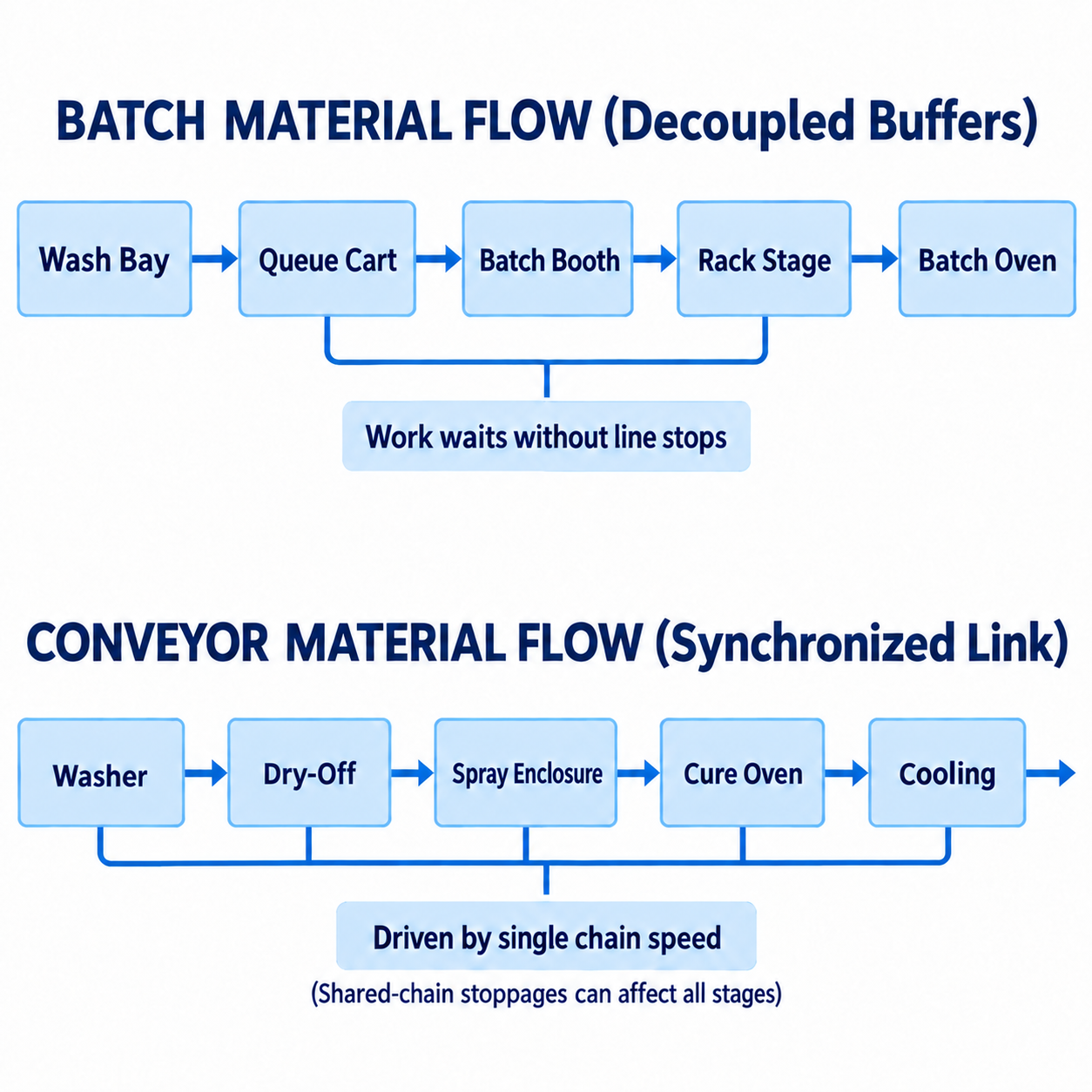
Diagram description
- BATCH MATERIAL FLOW (Decoupled Buffers)
- Wash Bay
- Queue Cart
- Batch Booth
- Rack Stage
- Batch Oven
- Work waits without line stops
- CONVEYOR MATERIAL FLOW (Synchronized Link)
- Washer
- Dry-Off
- Spray Enclosure
- Cure Oven
- Cooling
- Driven by single chain speed
- (Shared-chain stoppages can affect all stages)
- (Shared-chain stoppages can affect all stages)
- Wash Bay → Queue Cart
- Queue Cart → Batch Booth
- Batch Booth → Rack Stage
- Rack Stage → Batch Oven
- Washer → Dry-Off
- Dry-Off → Spray Enclosure
- Spray Enclosure → Cure Oven
- Cure Oven → Cooling
- Queue Cart → Work waits without line stops
- Rack Stage → Work waits without line stops
- Washer → Driven by single chain speed
- Dry-Off → Driven by single chain speed
- Spray Enclosure → Driven by single chain speed
- Cure Oven → Driven by single chain speed
- Cooling → Driven by single chain speed
- Batch: Wash Bay → Queue Cart → Batch Booth → Rack Stage → Batch Oven
- Queue Cart and Rack Stage connect via bracket to Work waits without line stops; not a process arrow
- Conveyor: Washer → Dry-Off → Spray Enclosure → Cure Oven → Cooling with outgoing arrow
- Bracket links all five conveyor stages to Driven by single chain speed; qualifier below bracket
The difference in thermal processing between these two approaches is just as significant. Continuous ovens rely on steady-state heat zones, air seals, or silhouetted entrance and exit vestibules to keep ambient heat from escaping into the plant. Conveyor speeds must provide enough dwell time for parts to reach temperature and hold it for the required cure window.
Batch ovens, by contrast, cycle from ambient or an idle hold up to setpoint temperature after doors are closed, requiring deliberate airflow patterns to bring dense racks up to heat evenly. When specifying batch equipment, reviewing powder-specific airflow and recording options ensures that high-velocity convection air does not disturb loose powder films on complex geometries before gelation occurs, while integrated chart recorders or digital data loggers verify that the actual substrate—not just the oven air—hit target parameters.
Test Each Architecture for Handling, Floor Space, and Interruptions
Evaluating equipment layouts on a facility floor plan requires looking past raw footprint dimensions to account for staging access, overhead clearance, and material buffers.
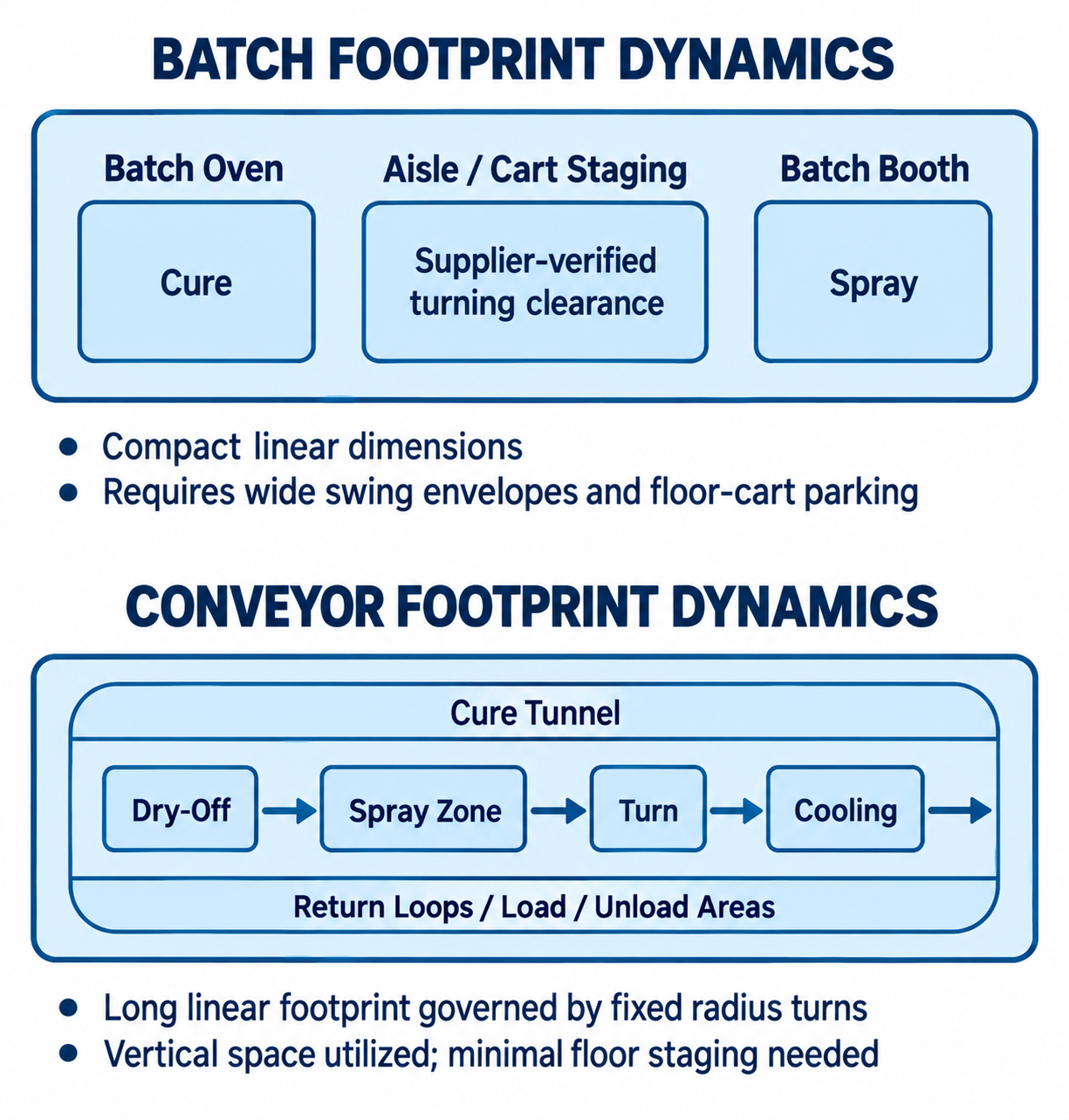
Diagram description
- BATCH FOOTPRINT DYNAMICS
- Batch Oven
- Cure
- Aisle / Cart Staging
- Supplier-verified turning clearance
- Batch Booth
- Spray
- Compact linear dimensions
- Requires wide swing envelopes and floor-cart parking
- CONVEYOR FOOTPRINT DYNAMICS
- Cure Tunnel
- Dry-Off
- Spray Zone
- Turn
- Cooling
- Return Loops / Load / Unload Areas
- Long linear footprint governed by fixed radius turns
- Vertical space utilized; minimal floor staging needed
- Dry-Off → Spray Zone
- Spray Zone → Turn
- Turn → Cooling
- BATCH FOOTPRINT DYNAMICS → Batch Oven: contains
- BATCH FOOTPRINT DYNAMICS → Aisle / Cart Staging: contains
- BATCH FOOTPRINT DYNAMICS → Batch Booth: contains
- Batch Oven → Cure: contains
- Aisle / Cart Staging → Supplier-verified turning clearance: contains
- Batch Booth → Spray: contains
- CONVEYOR FOOTPRINT DYNAMICS → Cure Tunnel: loop upper boundary
- CONVEYOR FOOTPRINT DYNAMICS → Return Loops / Load / Unload Areas: loop lower boundary
- BATCH FOOTPRINT DYNAMICS: outer footprint contains Batch Oven with Cure inside, Aisle / Cart Staging with Supplier-verified turning clearance inside, Batch Booth with Spray inside.
- Two bullet qualifiers below verbatim.
- CONVEYOR FOOTPRINT DYNAMICS: outer footprint encloses loop boundary labelled Cure Tunnel across top and Return Loops / Load / Unload Areas along bottom.
- Within loop Dry-Off → Spray Zone → Turn → Cooling → rightward exit arrow.
Neither architecture holds a universal advantage in floor space. A conveyor system can reduce rolling carts and floor staging by keeping work suspended overhead, but it requires substantial linear space for return loops, elevation changes, and structural support steel. Monorail turns require specific minimum radii to prevent rack binding, which expands the overall equipment envelope.
Batch systems can fit into tighter, compartmentalized footprints, but they demand wide aisles and designated cart-parking areas. If your facility lacks the turning clearance for a 20-foot rolling cart outside the oven door, the line will jam up regardless of how fast the burner brings the chamber to temperature.
Part geometry and racking weight also influence this balance. When investigating powder coating oven options, consider how your hanging configuration interacts with internal heat transfer. In a continuous tunnel, parts present a continuous, distributed profile to radiant emitters or convection air nozzles. In a batch oven, dense parts clustered on a multi-tier cart create aerodynamic shadowing.
Reviewing how your specific load configuration and airflow interact inside the oven prevents under-cured areas in the middle of a dense rack. If parts are packed too tightly to maximize a batch cycle, interior components will lag behind exterior components in reaching cure temperature.
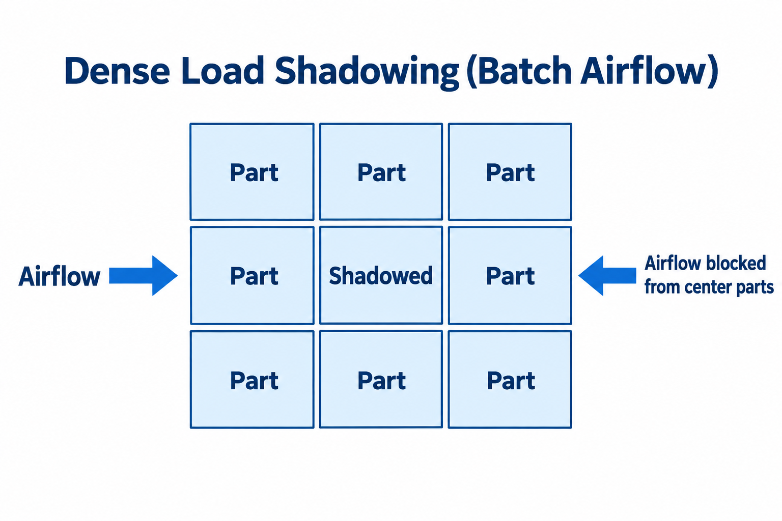
Diagram description
- Dense Load Shadowing (Batch Airflow)
- Airflow
- Part
- Shadowed
- Airflow blocked from center parts
- Title Dense Load Shadowing (Batch Airflow). 3 by 3 load grid; eight cells labeled Part; central cell labeled Shadowed.
- Airflow at left points RIGHT toward grid.
- Right label Airflow blocked from center parts points LEFT toward grid.
- Shadowed
- Part
- Airflow points right
- Airflow blocked from center parts points left
The most critical operational difference emerges during unexpected line stoppages:
- Conveyor Line Stoppage: A fault may require stopping a shared-chain conveyor, leaving parts inside the cure tunnel stationary. The effect depends on the conveyor controls, accumulation provisions, and line layout. While modern convection ovens with air seals handle brief pauses, extended stoppages risk overbaking, discoloration, or embrittlement of heat-sensitive coatings trapped in the cure zone.
- Batch Interruption: If an application gun fails in a batch booth, the cure oven completes its programmed cycle uninterrupted. The operator simply unloads the cured rack and waits to reload until the booth issue is resolved. The blast radius of the interruption remains isolated to that single station.
Validate the Choice with a Representative Production Plan
To choose the right architecture, run your actual weekly part mix through a comparative scheduling exercise rather than relying on abstract throughput targets.
Consider how two distinct manufacturing scenarios interact with these system choices:
Scenario A: Mixed-Gauge Job Shop
A commercial fabricator processes structural steel assemblies, 14-gauge enclosure panels, and small aluminum brackets. The schedule calls for four distinct powder colors per day, with production quantities varying from single prototypes to runs of fifty units.
- Conveyor Implementation: The line speed must be set slow enough to ensure the heavy structural components achieve full cure. Consequently, light sheet metal panels may spend longer in the cure tunnel than their own profile requires. Color switches can also create gaps in production, depending on booth changeover and conveyor arrangements.
- Batch Implementation: The shop groups work by gauge and chemistry. Sheet metal runs together on a fast cure cycle; heavy structural weldments run later on an extended soak cycle. Color changes take place between cart loads, with cleaning time included in the schedule. For this operational profile, batch architecture may support operational flexibility while each load’s cure profile is verified.
Scenario B: Dedicated OEM Product Line
An equipment manufacturer builds three standardized pump frames using consistent 10-gauge steel components. They run textured black polyester five days a week with occasional, scheduled shifts for safety yellow.
- Conveyor Implementation: Racks are custom-engineered to optimize hook density. Conveyor chain speed is locked to the precise thermal curve of 10-gauge steel. The dry-off, application, cure, and cooling zones run continuously with fixed staffing at the load and unload stations. This arrangement may support predictable throughput and reduce manual cart handling; quantify labor and work-in-process staging for the actual layout.
- Batch Implementation: Operators spend substantial labor manually loading, pushing, parking, and tracking carts between discrete operations. Include that handling labor and cart staging in the comparison. For this operational profile, continuous architecture may be a strong candidate if the validated throughput and total operating costs support it.
Validating Against Coating Cure Profiles
To confirm equipment capability during scheduling exercises, pull the exact technical data sheets for your primary coatings. For example, reviewing TIGER Series 89 cure parameters shows that achieving correct mechanical performance and film integrity for an interior epoxy-polyester depends strictly on substrate peak metal temperature (PMT) and dwell time—such as reaching 392°F (200°C) and holding it for the time window specified for that exact finish variant—rather than simple air temperature inside the box.
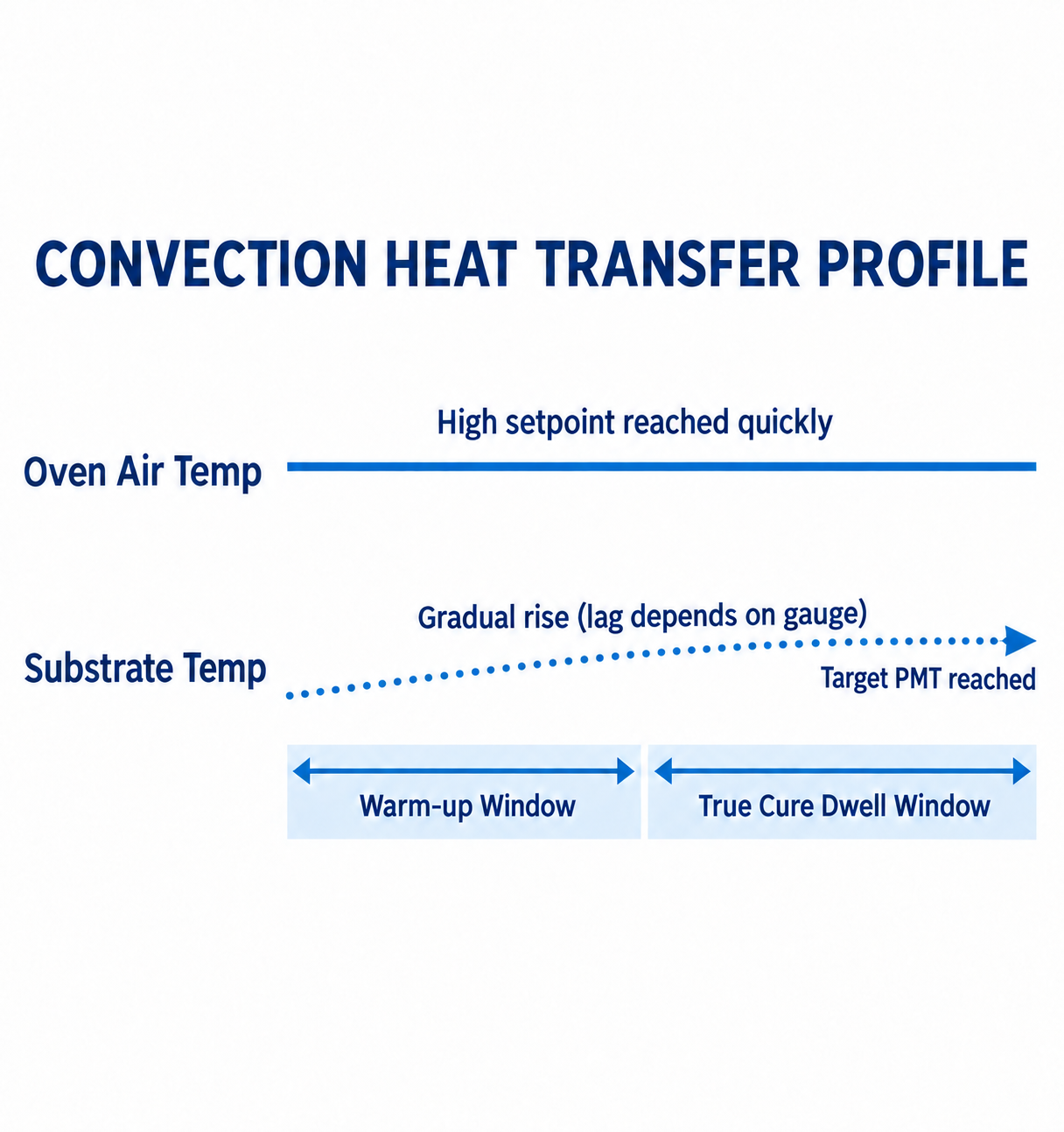
Diagram description
- CONVECTION HEAT TRANSFER PROFILE
- Oven Air Temp
- High setpoint reached quickly
- Substrate Temp
- Gradual rise (lag depends on gauge)
- Target PMT reached
- Warm-up Window
- True Cure Dwell Window
- Title CONVECTION HEAT TRANSFER PROFILE; two aligned horizontal schematic profiles labelled Oven Air Temp and Substrate Temp.
- Oven Air Temp solid high horizontal line labelled High setpoint reached quickly.
- Substrate Temp dotted gradual-rise representation labelled Gradual rise (lag depends on gauge), points right to Target PMT reached.
- Below are adjacent double-headed intervals Warm-up Window then True Cure Dwell Window.
- aligned schematic profiles
- none
If your part mix includes heavy castings alongside thin enclosures, processing both on the same unzoned, fixed-speed conveyor may constrain line speed or require separate production runs.
Before you build an oven quote specification, answer these five validation questions:
- What is the ratio of your thickest cross-section substrate to your thinnest substrate across a typical 40-hour production run?
- How many minutes per shift does your team currently spend cleaning spray equipment and changing powder hoppers?
- What is the physical footprint limit of your finishing bay, including the turning radii and cart buffer staging lanes outside equipment doors?
- How many manual operators will be dedicated exclusively to hanging, masking, spraying, and packing parts?
- What are the specific cure schedules (temperature versus time at metal temperature) for your three most frequently used powder formulations?
Moving from Evaluation to Equipment Specification
Once your part envelope, shift dynamics, and cure requirements are clearly defined, the equipment selection moves from high-level operational concepts to hard mechanical specifications. Sizing burners, choosing exhaust fans, engineering conveyor hang points, and configuring booth airflow all require accurate, real-world operating data.
Bring your part dimensions, daily color change targets, substrate thickness range, and facility dimensions to our engineering team to request a powder coating equipment quote. We will help you configure a batch or continuous layout matched directly to your workload, floor space, and production targets.