
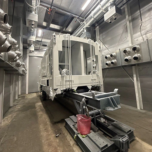
A paint booth is an exhaust engine. When the exhaust fan runs, it forcefully removes thousands of cubic feet of air per minute from the enclosure to clear overspray, solvent vapors, and particulate. That air does not disappear into a vacuum; it leaves the building entirely.
Makeup air exists to replace that evacuated volume deliberately. A makeup air system does not generate air out of nothing. It draws outside air, filters it, tempers it when necessary, and delivers it into the workspace along an engineered path. Without a designated replacement route, the building envelope itself becomes the intake, pulling unfiltered, unconditioned air through wall seams, door thresholds, unsealed windows, and unit heater flues.
The Replacement-Air Path: Mechanics of Exhaust and Intake
Air follows the path of least resistance. When an exhaust fan evacuates air from a spray cabin, the pressure inside drops relative to the surrounding space. If there is no dedicated supply duct feeding the booth, replacement air forces its way in from the adjacent plant environment.
- Outdoor replacement air reaches the cabin through the installed supply arrangement.
- Contaminated cabin air passes through exhaust collection and then the exhaust fan to the approved discharge.
If the building envelope is sealed tightly and lacks sufficient makeup air, the plant enters a negative pressure condition. The booth exhaust fan fights against this rising static pressure, moving less air than its mechanical rating dictates.
Over steady operation, mass entering the building balances mass leaving it. Volumetric ratings must be compared at consistent air conditions; this relationship is not a generic fan-sizing equation.
Every cubic foot of air exhausted through a paint booth stack, a weld extraction arm, or a roof-mounted mushroom fan must enter through an opening somewhere in the structure. Makeup air systems regularize this exchange. Instead of pulling dust from the warehouse floor or cold drafts through bay doors, an engineered system supplies clean, controlled replacement air directly where the process demands it.
Differentiating Exhaust, Supply, and Recirculation
Industrial finishing relies on three distinct air handling roles. Conflating them leads to poor finish quality, structural drafts, and code compliance failures.
| Air Stream | Primary Function | Source Air | Destination |
|---|---|---|---|
| Exhaust | Capture overspray and evacuate hazardous solvent vapors | Booth interior cabin | Discharged outside the facility |
| Makeup (Supply) | Replace evacuated air volume to stabilize building pressure | Fresh outside replacement air; configuration-specific supply arrangements | Booth cabin or surrounding plant |
| Recirculation | Reuse conditioned air where the approved system and operating mode permit it | Approved return-air source | Approved return path |
Exhaust systems are safety-critical. They prevent the accumulation of flammable vapors and extract airborne solids away from the operator's breathing zone and the wet workpiece.
Dedicated air makeup units supply replacement air to offset this exhaust. A comfort-HVAC system should not be assumed capable of providing this replacement-air load. Comfort cooling and heating systems are designed to recirculate indoor air through modest supply runs, cycling the same air mass while introducing only a small fraction of outside air for ventilation. An industrial paint booth demands continuous single-pass air exchange during spray applications.
Recirculating air during an active spray operation introduces severe fire and finish risks. Solvents build up quickly in a closed loop, degrading the finish and pushing VOC concentrations toward lower explosive limits. The cited GFS booth example recirculates during an engineered cure cycle; its building recirculation examples are separate configurations. Neither example authorizes generic spray-mode recirculation. Follow the installed system’s approved modes, safeguards, and applicable requirements.
Direct Booth Delivery Versus Facility-Level Supply
Replacement air enters finishing operations through one of two primary mechanical layouts: direct delivery to the cabin or general plant tempering.
In GFS’s air-replacement system guidance, replacement air is shown supplied directly into a pressurized booth plenum or introduced into the wider facility to satisfy the intake requirements of non-pressurized booths. The right configuration depends on cabin design, plant architecture, and shop cleanliness requirements.
| Arrangement | Replacement-air route |
|---|---|
| Direct booth supply | Outdoor air through the makeup-air unit and booth supply path into the cabin, then through the exhaust system |
| Facility-level supply | Outdoor air through the makeup-air unit into the plant, then from the plant into the booth and through the exhaust system |
Direct Booth Supply
Direct supply couples the air handler directly to the booth intake plenum. This layout is typical for pressurized cabins:
- Pressure Control: The supply fan delivers slightly more air than the exhaust fan removes (positive pressure), or slightly less (negative pressure), depending on process specifications. The specified pressure relationship can reduce infiltration through leakage paths, but does not guarantee clean conditions when doors open.
- Thermal Efficiency: Only the air passing through the spray cabin is heated or filtered to finishing standards, reducing dependence on conditioning the entire plant, while still interacting with the building.
- Isolation: The booth operates as a semi-contained thermodynamic system, minimizing interference from plant-wide pressure swings.
Facility-Level Supply
Facility-level supply dumps replacement air into the general shop volume rather than ducting it into the booth. An open-face or non-pressurized booth draws air from the shop; intake filtration depends on the booth design, and open-face booths may have no intake filter bank:
- Airpath Dependency: Intake air traverses the production floor before entering the booth. Any particulate generated between the air handler discharge and the booth intake can migrate toward the filters.
- Multi-Equipment Balancing: A single central unit can replace air evacuated by several small open-face booths, grinding hoods, or parts washers simultaneously.
- Building Envelope Relief: This approach directly mitigates building negative pressure, helping reduce pressure-driven drafts; fuel-appliance draft safety still requires appropriate verification.
Thermal Conditioning and Moisture Realities
Introducing outdoor air requires managing outdoor temperatures. When winter air enters an unheated spray booth, paint viscosity spikes, atomization suffers, and solvent flash times lengthen dramatically.
Industrial air handlers incorporate heating modules—typically direct-fired natural gas, indirect-fired heat exchangers, or hydronic coils—to bring cold supply air up to required application temperatures. Direct-fired burners place the flame directly in the airstream, achieving clean, efficient heat transfer, whereas indirect units route combustion byproducts through an isolated heat exchanger stack.
Heating air changes its relative humidity, but it does not remove water.
A burner increases the dry-bulb temperature of incoming air. As air warms, its capacity to hold water vapor increases, which causes its relative humidity (RH) to drop. However, the humidity ratio remains unchanged under sensible heating alone; a direct-fired gas burner can add water vapor through combustion.
If cold, rain-saturated air enters an air makeup unit at 40°F and 95% RH, heating it to 75°F drops its relative humidity significantly. The lower relative humidity does not establish moisture removal; combustion or other processes can also change the moisture content. When applying moisture-sensitive coatings, such as certain waterborne basecoats or plural-component urethanes, heating alone cannot prevent moisture-related defects. True humidity control requires mechanical cooling coils for condensation, reheat systems, or desiccant dehumidification equipment.
Data Needed for a Tailored Air-Replacement Assessment
Installing or rebalancing replacement air requires exact facility data. Generic rules of thumb fail because every facility has unique exhaust draws, ceiling heights, and envelope leakage rates.
Before planning mechanical modifications, compile these operational baselines:
- Nameplate Exhaust Capacity: Record the designed CFM and static pressure ratings for all spray booth exhaust fans.
- Operating Modes: Document cycle variations. Determine if the booth runs continuous single-pass exhaust, alternates between spray and bake modes, or cycles exhaust fans dynamically based on gun triggers.
- Ancillary Facility Exhaust: Inventory all non-booth exhaust equipment operating within the same airspace. Include dust collection drop pipes, welding fume extractors, plasma cutters, parts washers, and roof ventilators.
- Utility Infrastructure: Verify available natural gas supply pressure, gas line diameter, and spare electrical service capacity at the proposed unit location.
- Envelope Conditions: Note observable pressure effects around the facility, such as doors that resist opening or close with excessive force.
If the facility displays erratic booth drafts, dirt contamination on wet parts, or backdrafting flues, review the diagnostic steps for air-balance warning signs. When evaluating the operational costs, capital expenditure, and production gains associated with adding conditioned makeup air, consult the framework for a make-up air investment evaluation.
Once your team has assembled your equipment specifications, operating schedules, and facility layout details, talk with a finishing systems specialist with those details for an equipment-specific inquiry.