
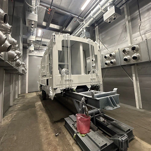
Setting a curing oven to 400°F does not mean parts are cured when the powder turns glossy. In industrial finishing, the air temperature inside the heating chamber is merely a medium, not the metric that dictates a complete cure. True curing is a chemical and thermal milestone that occurs inside the coating film itself, governed by the coating chemistry, the temperature of the underlying metal, and the duration of that exposure.
Understanding how an oven transfers energy into a part allows shop owners, production managers, and equipment buyers to prevent adhesion failures, under-cure brittleness, and unnecessary energy waste.
The Chemistry of the Cure: From Powder to Polymer
Visual smoothness does not equal a cured finish. When thermoset powder coats a cold metal component, it exists as a dry, finely ground blend of resins, pigments, curing agents, and flow modifiers held in place solely by electrostatic attraction. As heat enters the substrate, this dry layer progresses through distinct physical and chemical phases:
- Melt and Flow: As the surface warms, the individual powder particles soften, melt, and coalesce into a liquid film. Surface tension smooths out the peaks and valleys, causing the coating to wet out the substrate.
- Degassing: Trapped air and volatile reaction byproducts escape through the liquefied film.
- Gelation and Chemical Reaction: The fluid viscosity increases rapidly as chemical cross-linkers activate.
- Final Curing: The coating forms an insoluble, three-dimensional polymer network.
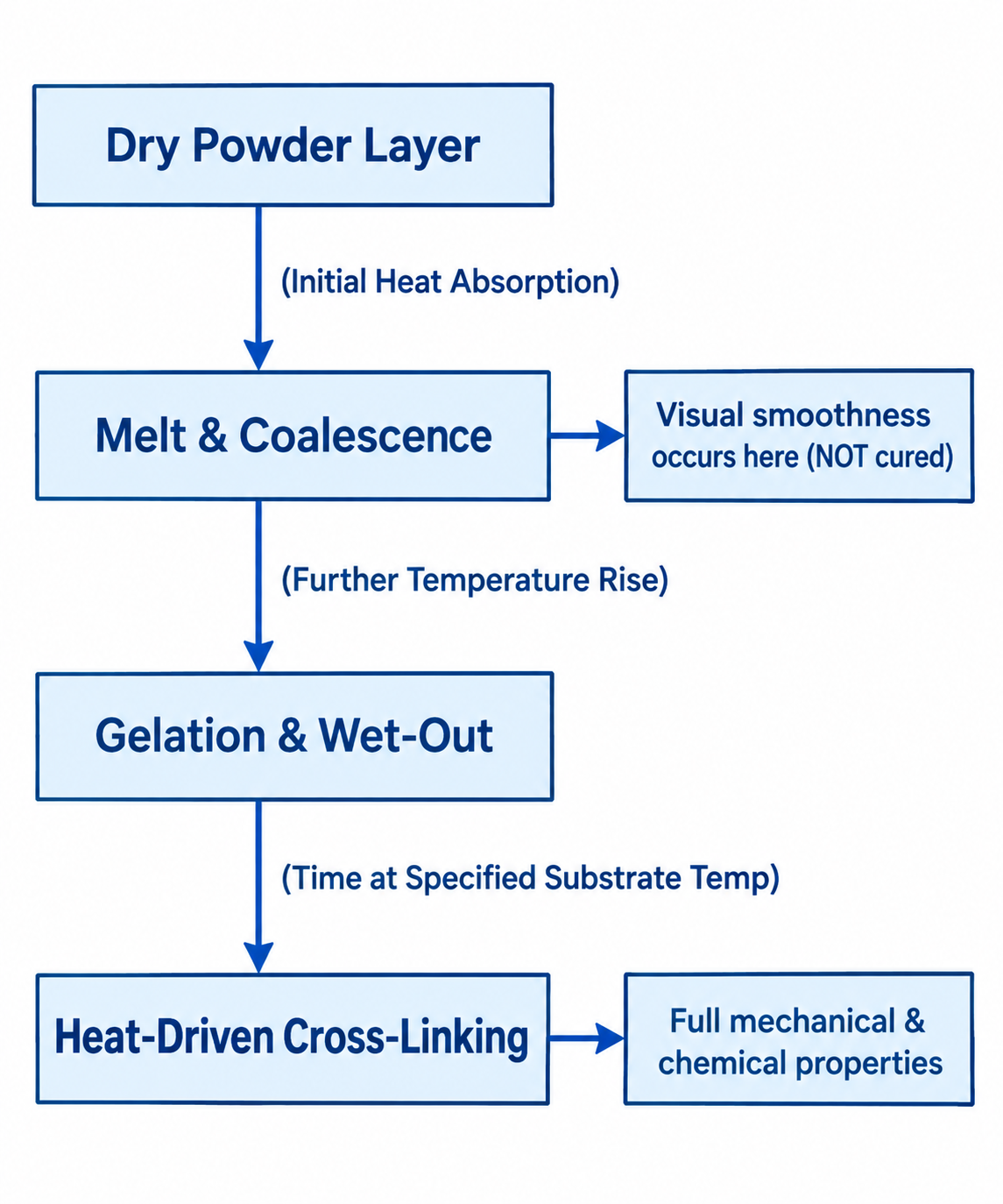
Diagram description
- Dry Powder Layer
- Melt & Coalescence
- Gelation & Wet-Out
- Heat-Driven Cross-Linking
- (Initial Heat Absorption)
- (Further Temperature Rise)
- (Time at Specified Substrate Temp)
- Visual smoothness occurs here (NOT cured)
- Full mechanical & chemical properties
- Dry Powder Layer → Melt & Coalescence: (Initial Heat Absorption)
- Melt & Coalescence → Gelation & Wet-Out: (Further Temperature Rise)
- Gelation & Wet-Out → Heat-Driven Cross-Linking: (Time at Specified Substrate Temp)
- Melt & Coalescence → Visual smoothness occurs here (NOT cured)
- Heat-Driven Cross-Linking → Full mechanical & chemical properties
- Vertical chain Dry Powder Layer → Melt & Coalescence → Gelation & Wet-Out → Heat-Driven Cross-Linking.
- Downward edge labels in order (Initial Heat Absorption); (Further Temperature Rise); (Time at Specified Substrate Temp).
- Melt & Coalescence has RIGHT side arrow to Visual smoothness occurs here (NOT cured).
- Heat-Driven Cross-Linking has RIGHT side arrow to Full mechanical & chemical properties.
That irreversible, permanent network forms through heat-driven cross-linking. While a finish may appear reflective, smooth, and dry to the touch just minutes after melting, the underlying polymer chains remain short and brittle if the reaction halts prematurely.
Without sufficient thermal energy over time, the film lacks tensile strength, corrosion protection, impact resistance, and chemical durability. Relying on visual appearance as an indicator of cure can allow under-cured parts to leave a powder coating operation.
The Cure Window: Why Air Temperature Misleads
To manage a curing line effectively, production teams must use a two-stage evaluation framework:
- Stage 1: Read the Powder Data Sheet
- Identify target substrate temperature and soak time
- Stage 2: Evaluate the Oven System
- Calculate heat-up lag, thermal mass, and true dwell time
First, identify the coating's specific time-at-temperature requirement from the manufacturer's Technical Data Sheet (TDS). Second, evaluate how the oven delivers that requirement to the specific part mass being processed.
A powder manufacturer's cure schedule does not refer to the ambient reading on an oven's digital controller. It refers explicitly to substrate temperature rather than oven air temperature.
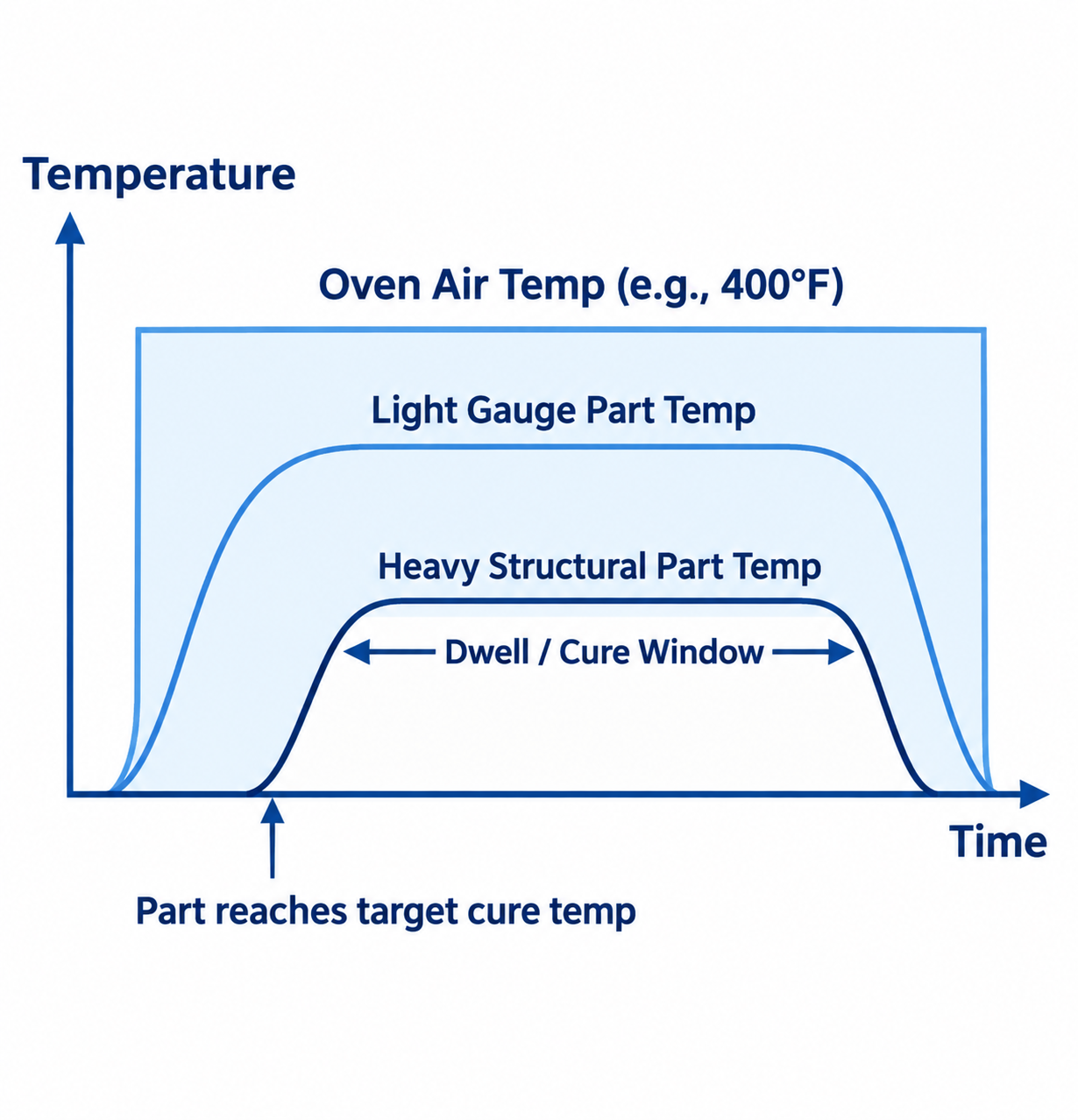
Diagram description
- Temperature
- Oven Air Temp (e.g., 400°F)
- Light Gauge Part Temp
- Heavy Structural Part Temp
- Dwell / Cure Window
- Time
- Part reaches target cure temp
- Temperature vertical upward axis, Time horizontal right axis.
- Oven Air Temp (e.g., 400°F) rectangular upper profile.
- Light Gauge Part Temp rises early to middle plateau and falls late.
- Heavy Structural Part Temp rises later to lower plateau and falls before light profile.
- Double-headed Dwell / Cure Window over heavy plateau.
- Upward annotation Part reaches target cure temp at start of heavy curve rising edge.
- Temperature
- Time
For example, looking at TIGER Series 89 cure parameters—a product line formulated for interior epoxy-polyester applications—the technical documentation specifies distinct time and temperature envelopes for the metal itself. For smooth glossy and smooth semi-gloss finishes, the published cure envelope includes holding the substrate at 392°F (200°C) for 8 to 10 minutes; 356°F (180°C) for 15 minutes also falls within that charted envelope. Textured finishes have a different window. The cure timer starts only when the substrate reaches that target temperature.
The Thermal Lag: Heavy Versus Light Loads
The gap between air temperature and metal temperature depends directly on thermal mass. Consider two very different workpieces processed in an oven running at a steady 400°F:
- Scenario A (Light Load): A run of 20-gauge steel sheet metal brackets has low thermal mass. They can reach the target metal temperature sooner than a much heavier load.
- Scenario B (Heavy Load): A weldment fabricated from 1/2-inch structural plate steel placed in the exact same oven may require a longer heat-up period before its metal reaches the target cure temperature.
If an operator starts a timer based on the oven controller reading 400°F, the sheet metal brackets may enter their cure window while the heavier plate is still heating. The plate could be pulled from the oven before its metal has spent the required time at the reaction temperature.
The coating on the heavy plate may look melted and glossy while still falling short of the required cure. Evaluating powder coating oven options requires matching heat delivery, burner capacity, and cycle timers to your heaviest production loads rather than your lightest parts.
Heat Delivery: Convection and Radiant Heating Roles
Industrial curing ovens rely on two primary methods of heat transfer: convection and radiation. Each method interacts differently with the part shape, color, and density of the load.
| Feature | Convection Ovens | Radiant (Infrared) Ovens |
|---|---|---|
| Primary Transfer Mode | Forced heated air (gas or electric) | Direct electromagnetic waves (IR) |
| Geometry Handling | Suits many complex, 3D weldments | Often suits flat, uniform, line-of-sight parts |
| Color / Emissivity Sensitivity | Less directly dependent on surface absorption | Absorption depends on coating and emitter wavelength |
| Airflow Speed | Moderate, balanced against powder blow-off | Minimal airflow required |
| Heat-Up Speed | Governed by convective transfer and load | Can provide rapid line-of-sight heating |
Convection Heating
Convection is the industry workhorse for general job shop and industrial coating lines. A heat source (typically a direct-fired natural gas burner or an electric element bank) warms an air stream, which high-capacity recirculation blowers circulate throughout the insulated cabin.
Convective transfer works by washing heated air across the part surfaces, breaking down the boundary layer of cooler air that naturally clings to cold steel. Because air can flow into pockets, channels, and internal corners, convection can heat complex shapes; uniformity still depends on airflow and loading.
However, air speed must be managed carefully. Recirculation blowers must deliver enough volume to transfer thermal energy rapidly, yet maintain a low enough discharge velocity at the supply ducts to prevent blowing dry powder off edges before it gels.
Radiant (Infrared) Heating
Radiant curing uses infrared (IR) emitters—powered by electricity or gas catalytic panels—to transmit electromagnetic energy directly to the part surface without relying on the surrounding air as a medium.
Infrared provides fast heat transfer and rapid gelation. It is often used as a booster stage on automated lines to quickly melt powder before parts enter a main convection oven, reducing the risk of cross-contamination and dust settling.
However, radiant energy travels in direct lines of sight. Surfaces facing the emitters heat quickly, while shaded surfaces, recessed corners, or interior channels lag behind. Furthermore, coating absorption and emitter wavelength influence how quickly a surface heats.
Because of these thermal dynamics, infrared suitability requires dedicated application trials on actual part profiles rather than generic heating assumptions.
Managing Airflow Patterns
When configuring an oven, load configuration and airflow design dictate whether heat reaches the center of a rack. Dense racking creates air-damming effects where outer parts absorb the convective heat, starving the center.
Ductwork placement—such as bottom-up supply with high-level returns or alternating side-wall louvers—must be tailored to part geometry to prevent cold zones. Factoring these requirements into your process helps you build an oven quote specification that prevents uneven curing across high-density racks.
Thermal Profiling and Process Verification
Because air temperature gauges do not indicate substrate conditions, a repeatable curing process relies on empirical data. Validating an oven requires profiling actual production parts under realistic loading conditions.
Multi-Channel Data Logger in Thermal Barrier Box
- Probe 1: Part 1 - Thin Cross-Section (Trailing Surface)
- Probe 2: Part 1 - Thick Core / Flange (Slowest to Heat)
- Probe 3: Ambient Air at Part Level
- Probe 4: Part 2 - Center of Rack (Airflow Shadow)
The Limits of Empty-Chamber Surveys
An empty-chamber temperature survey verifies that an oven's burner and recirculation fans disperse heat evenly throughout the empty volume. It does not account for the thermal load of actual production.
Introducing 2,000 pounds of cold structural steel creates an immediate thermal drop. The burner system must respond to this load, and the airflow must navigate around the parts to bring the metal up to target temperature. Process validation must be conducted on loaded racks using multi-channel data loggers protected by thermal barrier boxes.
Running a Part Profile
To map an accurate profile:
- Attach contact thermocouple probes directly to the thickest section of the heaviest part (the worst-case heat sink).
- Attach a second probe to the thinnest section of the lightest part to monitor against over-baking or discoloration.
- Attach a third probe to measure air temperature adjacent to the parts.
- Pass the data logger through the heating cycle alongside the workload.
The resulting curve shows the exact heat-up rate, the moment the substrate crosses into the cure window, the duration of the soak, and the cool-down phase.
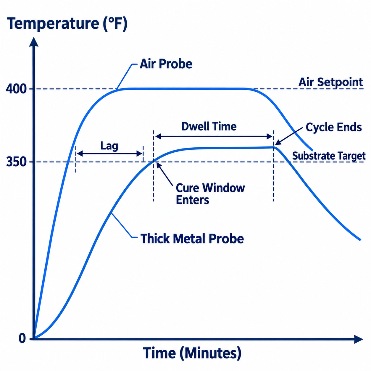
Diagram description
- Temperature (°F)
- 400
- Air Setpoint
- Air Probe
- 350
- Substrate Target
- Dwell Time
- Thick Metal Probe
- 0
- Time (Minutes)
- Lag
- Cure Window Enters
- Cycle Ends
- Temperature (°F)
- Time (Minutes)
- 0
- 350
- 400
- Air Setpoint
- horizontal dashed line
- Substrate Target
- Air Probe
- Rises sooner and reaches the 400 Air Setpoint before the thick-metal curve reaches its 350 Substrate Target.
- Thick Metal Probe
- Rises later/slower than Air Probe, crosses 350 Substrate Target after the air has heated, remains above the target during the Dwell Time, then cools after Cycle Ends.
- Its schematic soak plateau is below the 400 air-setpoint reference and above the 350 substrate-target reference; plateau temperature is not numerically specified.
- Lag
- Horizontal heat-up interval before thick-metal target attainment; no numeric duration.
- Cure Window Enters
- Thick Metal Probe crossing the 350 Substrate Target on heat-up.
- Dwell Time
- Cycle Ends
- 400 and 350 are retained illustrative levels from the source sketch.
- They are not a generic powder cure schedule, measurement results, or substitute for coating supplier TDS.
Post-Cure Quality Checks
Once the thermal profile confirms that parts hit their target dwell window, coating-supplier-specified mechanical and solvent checks provide additional evidence of film performance:
- Solvent Resistance (ASTM D5402): A solvent rub test can help assess solvent resistance when the powder supplier specifies the solvent, method, and acceptance criteria.
- Cross-Hatch Adhesion (ASTM D3359): A lattice pattern is cut through the film down to the substrate, covered with pressure-sensitive tape, and pulled away. Flaking or peeling along the grid indicates an adhesion problem that requires investigation; the test alone does not identify its cause.
- Impact Flexibility (ASTM D2794): Dropping a weighted indenter onto the coated surface tests the coating's elasticity. Compare the result with the powder supplier’s specified impact-performance criteria rather than diagnosing cure from cracking alone.
Modern industrial installations incorporate powder-specific airflow and recording options, allowing operators to monitor airflow rates, track burner output, and store digital batch records for every cure cycle. Documenting cycle profiles on your heaviest components gives you the operational baseline needed to optimize cycle times, avoid rework, and run a reliable finishing system.
Match Your Equipment to Your Actual Workload
Accurate curing requires balancing heating capacity, airflow patterns, and cycle timing against the thermal mass of your specific product mix.
Before committing to a curing configuration, document the dimensions and metal thicknesses of your heaviest components, your target rack densities, and the cure windows specified by your powder suppliers.
With that data in hand, you can contact an equipment specialist to review your production criteria and request a powder coating equipment quote tailored to your operational demands.