
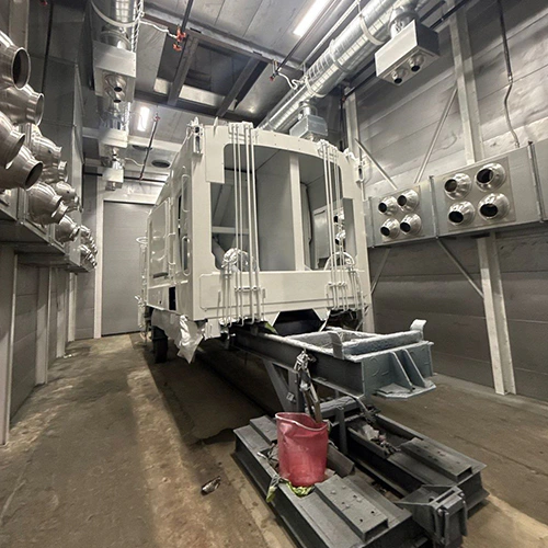
A complete paint booth maintenance program must reflect the specific machinery installed on your shop floor rather than a generic vendor checklist. Spray booths are integrated process enclosures combining mechanical ventilation, differential pressure monitoring, electrical interlocks, and life-safety systems. Treating maintenance as an informal walk-through or a simple filter swap creates blind spots that lead to finish defects, premature component failure, and safety liabilities.
Building an accountable maintenance scope requires defining every physical system, establishing who is qualified to service it, identifying the engineering standard or manual that governs the work, and recording empirical verification that the task was completed correctly.
- Cabin enclosure and lighting.
- Complete intake and exhaust airpath, filters, gauges, ducts, and stacks.
- Installed mechanical drives and thermal equipment.
- Installed safety controls and fire protection.
Defining the Scope Around Installed Equipment
Every booth configuration demands a tailored maintenance scope. A crossdraft booth exhausting directly through a rear wall has significantly different mechanical touchpoints than a downdraft booth with a heated air makeup unit (AMU), pit extraction, and variable frequency drives (VFDs).
Before building task lists, inventory the complete equipment profile:
- Cabin Enclosure: Wall and ceiling panels, entry and product doors, latching hardware, perimeter door gaskets, and observation windows.
- Air Movement & Filtration: Intake filter racks, ceiling diffusion media, pre-filtration banks, exhaust arrestors, differential pressure manometers, Magnehelic gauges, and exhaust ductwork.
- Mechanical Drives: Exhaust fan impellers, blower assemblies, drive belts, pulleys, motors, and shaft bearings.
- Heating & Make-Up Air (if equipped): Burner profiles, gas trains, heat exchangers, combustion air blowers, intake dampers, and temperature sensors.
- Electrical & Control Systems: Operator control consoles, airflow safety switches, purge cycle timers, motor starters, and solenoid interlocks.
- Illumination: Hazardous-location light fixtures, sealed glass lens covers, and perimeter lens gaskets.
- Safety & Life-Safety Equipment: Integrated fire suppression nozzles, release heads, thermal detectors, emergency stop circuits, and grounding cables.
Optional equipment reshapes this baseline. Adding an automated cure-cycle damper, a pneumatic roll-up door, or a regenerative thermal oxidizer adds mechanical actuators and safety interlocks that require dedicated service protocols.
In GFS’s dry-filter maintenance scope, maintenance routines are systematically categorized by equipment subsystem. This approach establishes baseline physical inspections for cabin components while adjusting operational service intervals based on running hours, spray application methods, and daily coating volumes.
The System Accountability Matrix
A functional scope assigns an explicit owner, a governing technical standard, and an inspection record for every subsystem:
| Subsystem | Scope of Work | Responsible Role | Method & Interval Source | Completion Evidence |
|---|---|---|---|---|
| Intake & Exhaust Filters | Loading assessment, frame seating, perimeter bypass checks, media replacement | In-House Operator / Maintenance | Differential pressure gauge reading & filter manufacturer load limits | Logged differential pressure drop, date, and filter model tracking |
| Cabin Structure & Seals | Latch tension, door seal compression, joint caulking, wall protection integrity | In-House Maintenance | Booth manufacturer assembly and maintenance instructions | Visual checklist with seal condition and hardware adjustment notes |
| Exhaust Fan & Drive | Belt tension and alignment, bearing lubrication, impeller overspray inspection | Certified Industrial Mechanic | OEM drive specifications and bearing manufacturer guidelines | Dynamic run test sign-off, belt deflection measurement log |
| Differential Pressure Gauges | Zero checks, sensing-line inspection, and fluid checks where specified | In-House Maintenance | Installed gauge manufacturer instructions | Zeroed gauge confirmation and static pressure verification sheet |
| Air Makeup & Burner | Gas train leak testing, flame safety lockout check, burner tuning, damper actuation | Qualified HVAC / Combustion Technician; licensing where required | Burner OEM technical manual and local fuel gas codes | Combustion efficiency printout and safety interlock test report |
| Electrical & Interlocks | Spray-to-exhaust fan interlocking, purge cycle validation, e-stop verification | Qualified Industrial Electrician | Electrical schematic and process safety control specifications | Functional trip-test record and control circuit sign-off |
| Fire Suppression | Piping integrity, nozzle covers, release mechanism, detection link inspection | Qualified Fire Protection Personnel; credentials where required | NFPA 33, NFPA 17, and local authority having jurisdiction (AHJ) | Formal inspection certificate and stamped compliance tag |
Cleanliness and the Airpath: Filtration, Housing, and Ducts
The airpath governs both transfer efficiency and fire safety. Airpath maintenance is not about cosmetic cleaning; it is about preserving the designed airflow pattern and controlling flammable particulate accumulation.
- Incoming air passes through the installed intake filtration into the working cabin.
- Overspray-laden air moves from the cabin through exhaust arrestors and the exhaust system.
- Particulate arrestors do not remove solvent vapors.
Intake and exhaust filtration serve two distinct functions:
- Intake Filtration: Designed to reduce airborne contaminants from the incoming airstream. It protects the wet coating from dirt seeds, fibers, and atmospheric dust.
- Exhaust Filtration: Designed to arrest overspray solids before they reach the exhaust plenum, fan blades, and exterior stack.
Dry particulate filters do not remove solvent vapors or volatile organic compounds (VOCs).
Particulate filters trap solid paint resins and pigments. Diluting and evacuating flammable solvent vapors requires adequate ventilation; particulate filtration does not provide vapor removal. Treating dry filters as a vapor-control measure is a dangerous operational error.
Filter fit is just as critical as filter media selection. A high-efficiency exhaust arrestor loose in its track or bowed by airflow pressure allows air to bypass the filter bank entirely. Unfiltered overspray then coats the fan impeller, unbalancing the assembly and creating heavy fire-load deposits in downstream ductwork.
Maintenance tasks must inspect media retention tracks, locking bars, and blanket hold-downs to ensure no gaps exist along filter edges.
Relying on arbitrary calendar dates to replace exhaust filters often leads to premature disposal of clean media or system choking under heavy production runs. Differential pressure gauges—such as inclined liquid manometers or mechanical dial gauges—measure static pressure drop across filter banks.
A standard paint booth maintenance calendar should dictate how frequently technicians inspect structural items, lubricate mechanical components, and zero out instrumentation. However, filter replacement decisions must follow documented pressure limits together with media condition, fit, compatibility, and other applicable requirements.
Housekeeping procedures inside the cabin must protect the equipment:
- Peelable protective booth coatings must be replaced when overspray accumulates heavily or begins peeling, which disrupts smooth airflow along cabin walls.
- Where fitted, include floor grates and pits in the approved cleaning scope, with required isolation and access procedures.
- Use cleaning tools and methods approved for the residue and work area under the facility’s procedures.
- Any vacuum must be approved for the actual hazardous atmosphere and collected material; an ordinary shop vacuum is not an appropriate substitute.
Mechanical, Controls, and Safety Responsibilities
Mechanical drives and life-safety systems present clear separation lines between operator-level checks and specialized trades. Blurring these lines leads to unaddressed mechanical failures or uncertified safety circuits.
| Operator and permitted in-house checks | Qualified trades and specialists |
|---|---|
| Visual condition, gauge logging, door seal observations, and approved housekeeping | Mechanical drive work, burner service, electrical and interlock testing, fire protection, and ventilation verification |
Exhaust fans operate downstream of the overspray collection system and can accumulate residue if collection or fit deteriorates. The mechanical scope must include:
- Fan Belts & Pulleys: Inspecting belt tension, checking for sidewall glazing or fraying, and verifying pulley alignment using a straight edge or laser tool. Loose belts slip, reducing fan speed and total exhaust volume; overtightened belts overload motor bearings.
- Bearings & Fan Impellers: Greasing bearings according to the manufacturer's specified lubricant type and duty cycle (avoiding over-greasing, which blows out bearing seals). Inspecting fan blades for overspray accumulation that causes vibration and motor strain.
- Door Latches and Compression Seals: Checking that latch assemblies maintain positive compression on perimeter gaskets without binding. Poor door seals can admit ambient shop dust when the pressure relationship draws air inward.
Electrical controls and process safety interlocks must undergo disciplined functional testing. Under OSHA’s spray-finishing maintenance provisions (29 CFR 1910.107), mechanical ventilation must remain active throughout spraying operations and continue for a safe period afterward to clear residual flammable vapors.
OSHA’s applicable electrical provisions distinguish equipment locations and exposure conditions and mandate that overspray residues be kept within controlled, cleanable boundaries. While OSHA enforces these continuous operating baselines, the standard does not prescribe an arbitrary, calendar-based third-party inspection interval.
Shop managers must design their program to verify that safety interlocks operate correctly at all times:
- Solenoid Interlocks: Verifying that the installed spray-equipment lockout responds as specified when ventilation is unavailable.
- Purge Timers: Testing the pre-ignition and pre-spray purge cycles to ensure the exhaust system runs unassisted for the complete engineered duration before heating or spray systems can activate.
- Emergency Stops: Verifying the documented emergency-stop sequence, including any ventilation required during a controlled shutdown.
Thermal systems and fire suppression require personnel qualified for the installed equipment under its OEM and system instructions. Servicing an air makeup unit’s gas train, burner nozzles, flame scanners, and modulating gas valves also requires any credentials or licensing mandated by applicable local rules.
Similarly, fire suppression systems governed by their applicable system standards and adopted codes must be inspected, serviced, and documented by personnel qualified under the installed system’s instructions and applicable adopted codes, including any required licensing or certification. In-house staff should perform only permitted visual checks and report damaged, obstructed, or missing components; nozzle positioning and protective covers must follow the installed system’s requirements.
Scheduling routine professional paint booth inspections establishes third-party technical oversight for complex safety interlocks, structural airflow testing, and major mechanical assemblies.
Lighting Enclosures and Structural Visibility
Paint booth lighting fixtures must illuminate the workpiece accurately while isolating electrical heat and wiring from the flammable application environment.
- Inspect lighting lens cleanliness, glass condition, and the enclosure’s specified seals or isolation boundaries.
- Electrical protection depends on the installed fixture and its location; do not infer a nonhazardous fixture interior from a pane alone.
Routine lighting care focuses on enclosure integrity:
- Lens Cleanliness: Overspray buildup on light fixtures drastically cuts booth lux levels, leading to poor coating uniformity and application defects. Use lens protection only where approved for the installed fixture; do not add coverings that compromise its protection or heat dissipation.
- Mechanical Integrity of Glass: Inspecting the tempered glass panes for stress cracks, chips, or deep scratches. Damaged glass panes must be replaced immediately to preserve the sealed boundary between the booth cabin and the fixture housing.
- Gasket Resiliency: Inspecting the elastomeric seals that frame each glass panel. Over time, baking heat and solvent vapors dry out and crack neoprene or silicone gaskets, breaking the vapor seal and allowing flammable vapors into electrical raceways.
Upgrading fixtures is a capital project, not a routine maintenance task.
Replacing older T8 fluorescent housings with industrial LED fixtures offers better lumen maintenance and lower operating costs, but it must be handled as an engineered retrofit. A technician cannot simply mount non-rated LED strips inside a spray booth.
Retrofit kits and replacement fixtures must be suitable for the actual installation, hazardous-location classification, and booth requirements, with applicable listing and approval verified.
Closure, Work Order Handoffs, and Verification
A checked box on a generic clipboard is not proof of maintenance. A defensible maintenance record requires five specific elements for every service event:
- Initial Condition: The baseline reading or physical observation before work began (for example: the measured exhaust pressure and observed belt condition).
- Specific Action Taken: The exact corrective procedure performed (for example: replaced exhaust arrestors with OEM-specified fiberglass/polyester blanket; tensioned exhaust fan belt to manufacturer deflection specification).
- Qualified Owner: The printed name, signature, and trade role of the individual who performed the work.
- Governing Criteria: The reference point used to determine pass/fail (such as the booth manual’s pressure limits or an OEM belt tension chart).
- Post-Service Verification: Empirical confirmation that the system operates within normal limits after service (for example: pressure within documented limits, correct specified fan rotation, and no abnormal vibration).
- Maintenance disposition log: record date, equipment ID, qualified owner, initial condition, action taken, actual governing manual criteria, and post-service verification.
- Use the specific equipment’s documented limits; sample pressures and invented manual references are not acceptance criteria.
Maintaining disciplined filter inspection records provides trend data that reveals developing airflow problems long before a component fails. A sudden drop in filter differential pressure can indicate bypass, a change in airflow, or a sensing fault and requires investigation.
Conversely, an unusually sharp rise in operating pressure after a short production run can reflect faster loading, changed airflow, media selection, or a sensing fault.
When your team encounters systemic issues—such as chronic cabin air imbalance, unexplainable pressure drops across the ductwork, or persistent burner safety lockouts—internal handoffs must transfer cleanly to specialized external resources. Knowing where in-house preventive maintenance stops and qualified specialist work begins protects your equipment and your operators.
Structuring Your Facility's Maintenance Program
To refine your facility's maintenance scope, identify gaps in your service procedures, or review operational performance against your booth's original design specifications, talk with a finishing systems specialist. Providing your booth model, its current operating hours, and the specific mechanical or airflow questions you are managing helps pinpoint the right procedures and technical standards for your shop floor.