
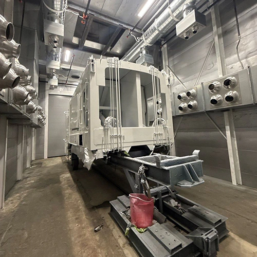
Choosing between wet and dry abrasive blasting determines how your facility handles dust containment, wastewater, surface cleanliness, and worker safety. Dry blasting can deliver aggressive cutting action without adding process water, but requires dust control and surface acceptance checks before coating. Wet blasting suppresses visible airborne particulate and may assist salt removal, but introduces water management, damp waste, and flash-rust considerations.
Evaluating these methods requires examining the equipment mechanics, the required metallurgical profile, post-blast processing steps, and regulatory obligations.
Process Mechanics and Equipment Configurations
Dry abrasive blasting uses compressed air to accelerate dry media through a blast nozzle directly onto the substrate. The impact pulverizes coatings, mill scale, and friable abrasive, generating high volumes of airborne dust that demand dedicated containment and continuous negative-pressure air filtration.
Wet abrasive blasting introduces water into the blast stream to cushion media impact, increase mass at the nozzle, and wash down particulate upon contact. How water joins the process fundamentally changes operating complexity, media consumption, and water volume.
The industry uses three primary wet configurations:
- Halo Rings (Water Curtains): A manifold ring mounts around the outside of a standard dry blast nozzle. Water sprays outward in a conical jacket that envelopes the dry air-and-abrasive stream after it exits the nozzle tip. This can retrofit a compatible dry system; water demand, dampening, and runoff depend on the selected nozzle and setup.
- Water Injection Nozzles: Water enters under hydraulic pressure directly inside the nozzle bore, mixing with the air and abrasive just before discharge. Water use, mixing quality, and nozzle wear depend on the selected design and operating conditions.
- Pressurized Vapor Abrasive Systems: Water and abrasive mix inside a pressurized vessel before being metered into the main airflow. Because media grains are encapsulated in a thin water jacket before introduction to the blast hose, the system can meter the mixture and limit water use within its designed operating range.
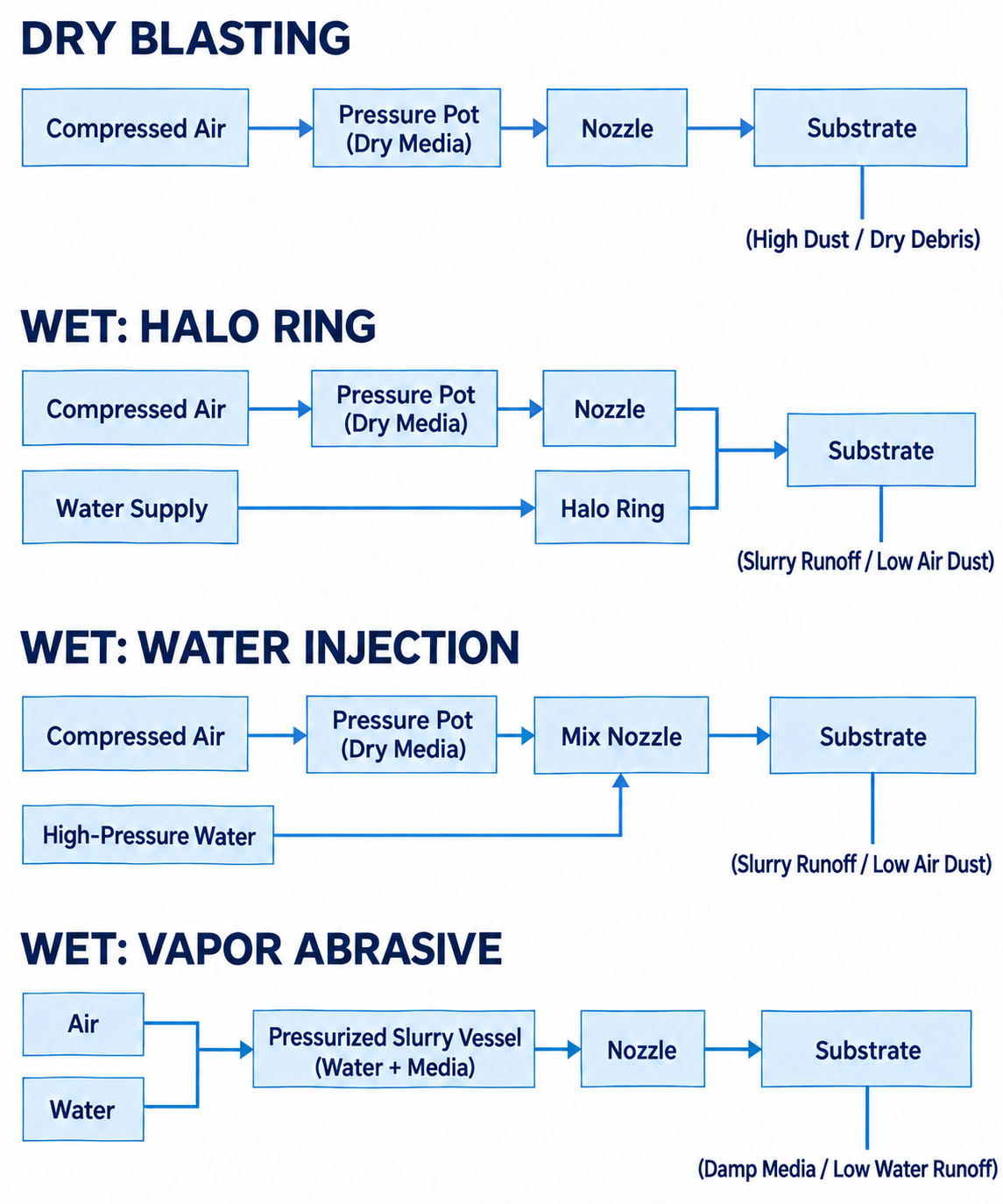
Diagram description
- DRY BLASTING
- Compressed Air
- Pressure Pot (Dry Media)
- Nozzle
- Substrate
- (High Dust / Dry Debris)
- WET: HALO RING
- Water Supply
- Halo Ring
- (Slurry Runoff / Low Air Dust)
- WET: WATER INJECTION
- Mix Nozzle
- High-Pressure Water
- WET: VAPOR ABRASIVE
- Air
- Water
- Pressurized Slurry Vessel (Water + Media)
- (Damp Media / Low Water Runoff)
- Compressed Air → Pressure Pot (Dry Media): dry/halo/injection
- Pressure Pot (Dry Media) → Nozzle: dry/halo
- Nozzle → Substrate: dry/halo/vapor
- Water Supply → Halo Ring: halo
- Halo Ring → Substrate: halo; merges with Nozzle
- Pressure Pot (Dry Media) → Mix Nozzle: injection
- High-Pressure Water → Mix Nozzle: injection; upward entry
- Mix Nozzle → Substrate: injection
- Air → Pressurized Slurry Vessel (Water + Media): vapor; merge
- Water → Pressurized Slurry Vessel (Water + Media): vapor; merge
- Pressurized Slurry Vessel (Water + Media) → Nozzle: vapor
- DRY BLASTING
- Compressed Air
- Pressure Pot (Dry Media)
- Nozzle
- Substrate
- (High Dust / Dry Debris)
- WET: HALO RING
- Compressed Air
- Pressure Pot (Dry Media)
- Nozzle
- Water Supply
- Halo Ring
- Substrate
- (Slurry Runoff / Low Air Dust)
- WET: WATER INJECTION
- Compressed Air
- Pressure Pot (Dry Media)
- Mix Nozzle
- High-Pressure Water
- Substrate
- (Slurry Runoff / Low Air Dust)
- WET: VAPOR ABRASIVE
- Air
- Water
- Pressurized Slurry Vessel (Water + Media)
- Nozzle
- Substrate
- (Damp Media / Low Water Runoff)
- Four independent panels preserve exact headings.
- DRY BLASTING: Compressed Air → Pressure Pot (Dry Media) → Nozzle → Substrate; Substrate has unheaded downward qualifier (High Dust / Dry Debris).
- WET: HALO RING: Compressed Air → Pressure Pot (Dry Media) → Nozzle; Water Supply → Halo Ring; Nozzle and Halo Ring merge then → Substrate; qualifier (Slurry Runoff / Low Air Dust).
- WET: WATER INJECTION: Compressed Air → Pressure Pot (Dry Media) → Mix Nozzle → Substrate, High-Pressure Water enters Mix Nozzle via upward arrow; same runoff qualifier.
- WET: VAPOR ABRASIVE: Air and Water merge → Pressurized Slurry Vessel (Water + Media) → Nozzle → Substrate, qualifier (Damp Media / Low Water Runoff).
Enclosure designs reflect these mechanical differences. Facilities reviewing indoor sandblasting booth options must distinguish between dry booths—which may use downdraft or crossdraft airflow, compatible media recovery, and dust collection—and wet-compatible enclosures. Wet operations need water containment and waste handling matched to the process, plus any exhaust filtration suitable for moisture and particulate.
Surface Profiles, Substrates, and Contamination
Both methods can alter the surface; media shape and size, substrate, equipment, and operating conditions determine the resulting profile and cleaning action.
Profile Geometry and Media Action
Dry blasting uses media impact to remove contaminants and develop a surface profile; angular abrasives and round beads produce different results.
Wet blasting modifies this impact. Water changes the impact and dust behavior, but does not by itself establish the final profile:
- Peak Shape: Wet and dry methods can produce different profiles, but peak shape and depth depend on the media, substrate, and process; verify a representative trial.
- Media Breakdown: Media breakdown and reuse depend on the abrasive and process. Added water changes recovery and separation requirements.
Achieving a clean surface requires aligning media hardness, mesh size, and blast pressure with established surface preparation fundamentals to hit the exact profile depth (e.g., 2.0 to 3.5 mils) required by the subsequent coating system.
Soluble Salt Removal
A potential advantage of wet blasting is assistance with non-visible contaminant removal. Dry blasting removes rust and scale, but does not by itself establish acceptable levels of soluble salts in surface pits. When encapsulated beneath a newly applied protective coating, trapped salts draw moisture through the paint film via osmosis, causing premature blistering and under-film corrosion.
Clean process water may help dissolve and flush soluble salts, but residual contamination must be checked against the project specification.
Thermal Stress and Thin Substrates
Dry blasting generates friction heat at the nozzle contact zone. On thin sheet metal, composite structures, or heat-treated alloys, heat and mechanical impact can contribute to warping, oil-canning, or dimensional distortion, depending on the part and process.
The continuous fluid flow in wet blasting acts as a heat sink. It can limit heat buildup, but mechanical impact can still distort thin panels or sensitive parts; validate the process on representative material.
Drying Cycles, Flash Rust, and Waste Streams
Post-blast operational requirements dictate whether wet or dry blasting fits your facility flow.
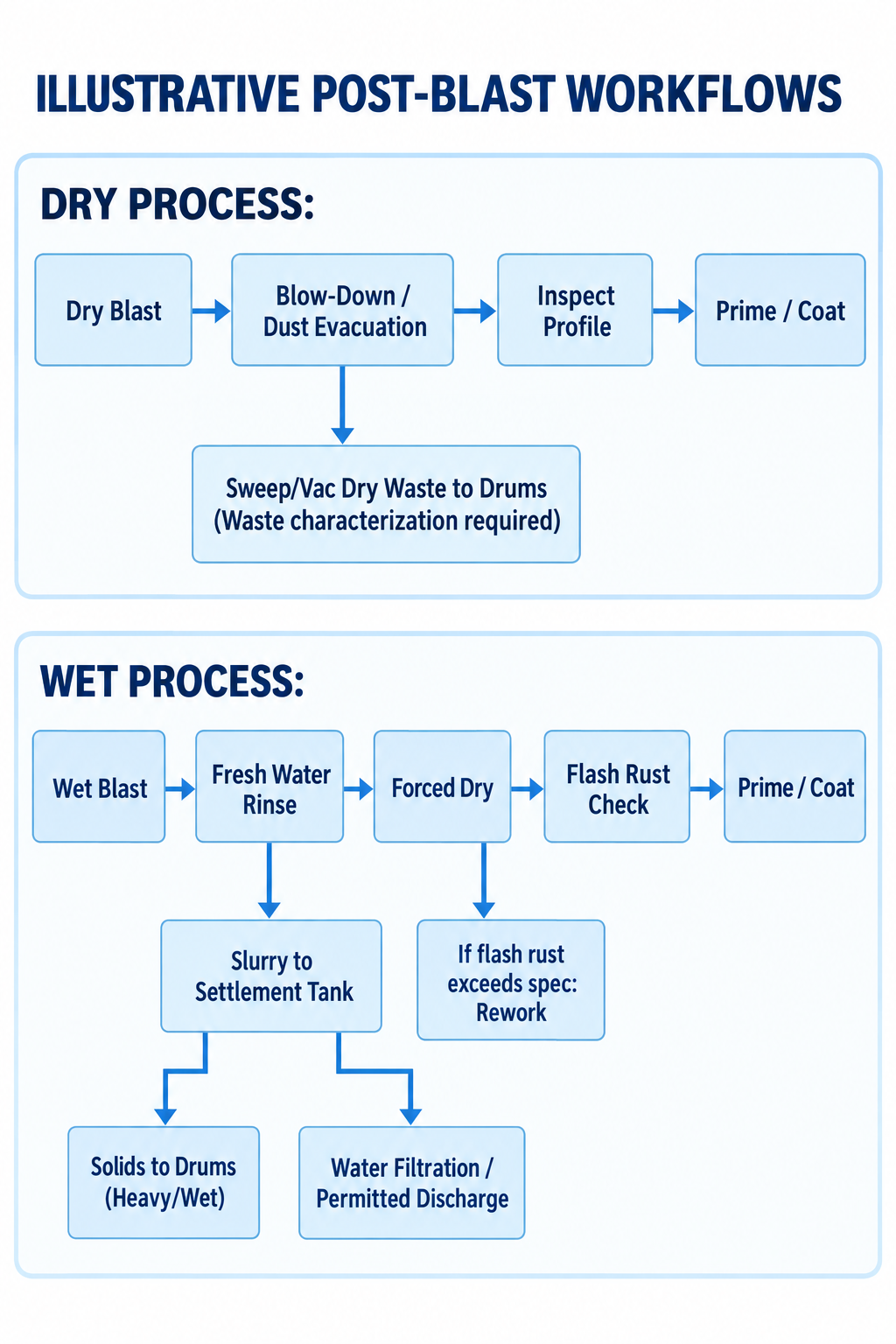
Diagram description
- ILLUSTRATIVE POST-BLAST WORKFLOWS
- DRY PROCESS:
- Dry Blast
- Blow-Down / Dust Evacuation
- Inspect Profile
- Prime / Coat
- Sweep/Vac Dry Waste to Drums (Waste characterization required)
- WET PROCESS:
- Wet Blast
- Fresh Water Rinse
- Forced Dry
- Flash Rust Check
- Prime / Coat
- If flash rust exceeds spec: Rework
- Slurry to Settlement Tank
- Solids to Drums (Heavy/Wet)
- Water Filtration / Permitted Discharge
- Dry Blast → Blow-Down / Dust Evacuation
- Blow-Down / Dust Evacuation → Inspect Profile
- Inspect Profile → Prime / Coat
- Blow-Down / Dust Evacuation → Sweep/Vac Dry Waste to Drums (Waste characterization required)
- Wet Blast → Fresh Water Rinse
- Fresh Water Rinse → Forced Dry
- Forced Dry → Flash Rust Check
- Flash Rust Check → Prime / Coat
- Forced Dry → If flash rust exceeds spec: Rework
- Fresh Water Rinse → Slurry to Settlement Tank
- Slurry to Settlement Tank → Solids to Drums (Heavy/Wet)
- Slurry to Settlement Tank → Water Filtration / Permitted Discharge
- Dry Blast → Blow-Down / Dust Evacuation → Inspect Profile → Prime / Coat
- Blow-Down / Dust Evacuation → Sweep/Vac Dry Waste to Drums (Waste characterization required)
- Wet Blast → Fresh Water Rinse → Forced Dry → Flash Rust Check → Prime / Coat
- Forced Dry branches to If flash rust exceeds spec: Rework
- Fresh Water Rinse branches to Slurry to Settlement Tank
- Slurry to Settlement Tank branches separately to Solids to Drums (Heavy/Wet) and Water Filtration / Permitted Discharge
Flash Rust Dynamics
When clean, active carbon steel contacts moisture and oxygen, oxidation begins within minutes. This rapid formation of light-to-moderate corrosion across the newly exposed profile is flash rust.
Several variables determine flash rust speed and severity:
- Evaporation Rate: High ambient relative humidity, low temperatures, and poor air movement retard surface drying, accelerating oxidation.
- Water Quality: Tap water containing dissolved minerals, hard salts, or high chloride counts accelerates the electrochemical corrosion cell. Cleaner rinse water may help limit flash rust; the actual result depends on the water and surface.
- Contaminant Clearance: If soluble salts are washed away thoroughly, the steel resists flash rust longer than steel holding residual chemical contamination.
Chemical Inhibitors and Coating Compatibility
Facilities often consider chemical flash rust inhibitors to delay oxidation between wet blasting and primer application. Inhibitors are chemical additives introduced during blasting or in the final rinse pass.
However, some inhibitors leave chemical residues on the steel substrate. The specific coating manufacturer’s technical data sheet governs whether chemical inhibitors are permitted.
Some coating or project specifications restrict inhibitors because residues can affect adhesion or coating performance. If your project specification bans chemical additives, review drying, environmental control, and the permitted time before coating with the process and coating suppliers.
Waste Stream Management
Waste handling presents fundamentally different challenges for wet and dry operations:
| Waste Parameter | Dry Blasting | Wet Blasting |
|---|---|---|
| Physical State | Dry, free-flowing particulate | Heavy slurry and liquid runoff |
| Separation Requirements | Standard dust collector hoppers; sweep or vacuum recovery | Multi-stage settlement weir tanks, mechanical filtration, or filter presses |
| Disposal Weight | Dry weight of media plus removed coating | High weight; sludge retains substantial moisture unless mechanically pressed |
| Discharge Permitting | Review dust/emissions and waste rules | Review containment/discharge and waste rules |
| Toxicity Profiling | Characterization for the actual waste stream | Characterize solids and liquid for their intended disposition |
Facility Safety, Regulatory Compliance, and Supplier Validation
Equipment selection involves critical facility safety requirements that counter common operational assumptions.
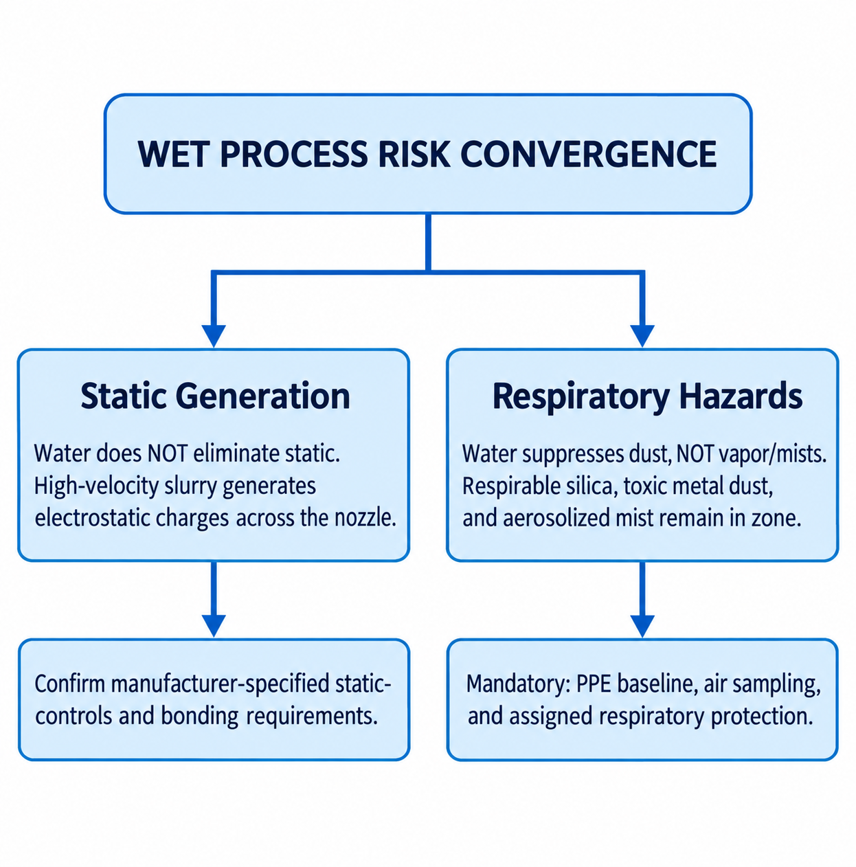
Diagram description
- WET PROCESS RISK CONVERGENCE
- Static Generation
- Water does NOT eliminate static.
- High-velocity slurry generates electrostatic charges across the nozzle.
- Confirm manufacturer-specified static-controls and bonding requirements.
- Respiratory Hazards
- Water suppresses dust, NOT vapor/mists.
- Respirable silica, toxic metal dust, and aerosolized mist remain in zone.
- Mandatory: PPE baseline, air sampling, and assigned respiratory protection.
- WET PROCESS RISK CONVERGENCE → Static Generation
- WET PROCESS RISK CONVERGENCE → Respiratory Hazards
- Static Generation → Confirm manufacturer-specified static-controls and bonding requirements.
- Respiratory Hazards → Mandatory: PPE baseline, air sampling, and assigned respiratory protection.
- Static Generation → Water does NOT eliminate static.: qualifier
- Static Generation → High-velocity slurry generates electrostatic charges across the nozzle.: qualifier
- Respiratory Hazards → Water suppresses dust, NOT vapor/mists.: qualifier
- Respiratory Hazards → Respirable silica, toxic metal dust, and aerosolized mist remain in zone.: qualifier
- WET PROCESS RISK CONVERGENCE branches into two parallel columns Static Generation and Respiratory Hazards.
- Each contains its exact two explanatory sentences and then downward arrow to its exact action text.
- No connection between the columns.
Static Electricity and Ignition Hazards
A persistent industry misconception claims that introducing water eliminates static electricity and combustion risks. This is dangerous.
The high-velocity transit of abrasive particles, water, and compressed air through non-conductive blast hoses and nozzle assemblies generates significant electrostatic charges. Equipment manuals for wet and vapor abrasive systems explicitly warn of static-sparking hazards. If operators work in confined spaces, marine tanks, or processing plants containing flammable vapors or combustible dusts, an ungrounded wet-blast stream can discharge a static spark capable of ignition.
The selected equipment’s manual governs grounding, bonding, compatible hoses, and use around ignition hazards; water does not waive those requirements.
Respiratory Protection and Regulatory Exposure
Another common assumption is that suppressing visible dust eliminates the need for blast respirators. Regulatory standards reject this premise.
Under OSHA interpretations governing abrasive blasting, suppressing visible dust does not waive the requirement for personal respiratory protection or engineering hazard controls. Wet blasting knocks down heavier dust particles, but fine respirable dust, aerosolized mist, and toxic particulates remain suspended within the operator’s breathing zone.
If the blasted coating contains lead, cadmium, or hexavalent chromium, or if the media generates respirable crystalline silica, that toxicity transfers directly into the wet mist and airborne droplets.
A facility cannot drop down to standard particulate masks simply because the process runs wet. Respiratory selection must be verified through real-world, task-based industrial hygiene air monitoring under actual operating conditions within your enclosure.
Supplier Evaluation Checklist
Before speaking with an equipment manufacturer or engineering firm to request a blast booth quote, gather specific operational metrics. Because equipment sizing, airflow dynamics, and filtration footprints vary significantly, your supplier will require hard project parameters rather than general estimates.
Use this checklist to structure your vendor inquiries:
- [ ] Substrate & Geometry Profile: What are your part dimensions, material grades, wall thicknesses, and sensitivity to thermal distortion?
- [ ] Coating System Constraints: Does the protective coating specification mandate an angular versus peened anchor tooth? Does it strictly prohibit chemical flash rust inhibitors?
- [ ] Target Cleanliness Standard: What level of surface cleanliness (e.g., SSPC-SP 10 / NACE No. 2 Near-White vs. SSPC-SP 5 / NACE No. 1 White Metal) must you maintain continuously across production?
- [ ] Enclosure Infrastructure: If wet, does the facility floor allow trenching for gravity sumps, or will your process demand above-ground water catchment, weir settling tanks, and pump-assisted filtration?
- [ ] Utility Capacity: Can your facility supply the required dry compressed air (CFM and PSI at continuous duty) alongside clean water at the pressure and volume specified by the blast system?
- [ ] Wastewater & Environmental Permitting: What are the local municipal limits regarding sewer discharge of heavy metals, suspended solids (TSS), and pH from rinse water?
- [ ] Static Mitigation Protocols: Does the supplier’s package include integrated static-conductive blast hoses, deadman safety interlocks, and dedicated earth-grounding equipment for flammable atmospheres?