Start with the spray gun’s documented inlet requirement and the point where its manufacturer expects pressure to be checked. Run the gun under the repeatable production condition that causes trouble, then record pressure at the gun, the booth branch, after central treatment, and the receiver outlet while the same demand remains active.
Read those locations as one path. If pressure holds at the receiver but falls farther downstream, the first meaningful change narrows the search to treatment equipment, shared piping, or the final booth connection. Pipe length, internal diameter, fittings, valves, regulators, couplers, and hose then explain what that segment contains. Static readings cannot show the same loss because resistance changes with airflow. This sequence separates a supply change from distribution loss before higher system pressure or more compressor capacity enters the discussion.
Check pressure where the gun uses it
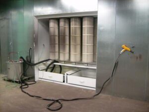
Begin with the spray-gun manual and the coating setup in use. The pressure and flow requirement belongs to that gun, air cap, and operating mode; a setting copied from another model doesn’t establish the target. Note where the manufacturer expects pressure to be checked, because a wall regulator and a gauge at the gun inlet don’t describe the same point.
Then observe the gun while air is flowing under the production condition that causes trouble. With the trigger closed, flow through the path falls sharply and so does flow-related pressure loss. That static reading answers only one question: what pressure is present while the line rests? It cannot show what reaches the gun during atomization.
A near booth and a far booth make the difference easy to see. Both drops may show the same static pressure. Once the guns operate under comparable conditions, the near gun may hold its required inlet pressure while the far gun falls below its target. Distance is not yet the diagnosis. The result simply proves that the far endpoint needs a pressure trace while air is moving.
Trace every pressure loss from receiver to gun
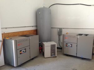
Follow the air in order. Start at the receiver outlet, continue through the dryer and filters, mark the main header and booth branch, then finish with the regulator, couplers, and hose. Each item contributes some resistance. Several modest losses can add up even when no single component appears dramatic.
Three or four readings usually tell a much better story than one gauge. Record pressure at the receiver outlet, after central treatment, at the booth branch entrance, and at the gun inlet while the same demand event remains active. When practical, use matched instruments or move the same suitable instrument between points during repeated runs so gauge differences don’t masquerade as system changes.
The location of the first meaningful change directs the next inspection:
| What the readings show | Where to look next |
|---|---|
| Receiver pressure changes as demand starts | Supply and storage remain part of the investigation |
| Pressure holds at the receiver but changes after treatment | Dryer, filter, separator, valves, and their current condition |
| The shared main loses pressure before branches divide | Main-line route, fittings, valves, and combined flow |
| Branch entrance holds but gun inlet changes | Local regulator, connectors, hose, and gun-side hardware |
These patterns locate a section; they don’t name a failed part. That distinction prevents a shop from replacing the nearest visible component when the larger loss sits somewhere else.
See how layout turns flow into pressure drop
Pressure drop grows out of the route the air must travel and the flow that route carries. Longer pipe presents more internal surface. Elbows, tees, valves, and other fittings add resistance beyond their measured length. For a given flow and starting pressure, a smaller internal diameter raises air velocity and pressure loss. A rough internal bore also adds friction; corrosion can make an older steel line rougher than it was when installed.
The branch pattern decides how those factors combine. An outlet at the end of a trunk receives air through the full path back to the supply. A loop can feed an outlet from two directions, shortening the effective travel distance and dividing some of the flow. That can reduce distribution loss, but it does not make a loop the automatic answer for every building. Pipe size, route, expected demand, material, and component ratings still belong in a system-specific design.
Fittings also explain why two branches of similar floor-plan length can perform differently. One may follow a direct run; the other may pass through more turns, valves, and branch connections before reaching the booth. The difference becomes larger when several tools share the upstream header.
Add those details to the route sketch: measured run lengths, internal diameter where known, pipe material and visible condition, fittings, branch points, and every user that shares the path. Paint Booth’s Prevost Air page shows the kind of distribution layout that can be planned around actual equipment locations rather than guessed from straight-line distance.
Compare the near gun with the far booth under the same load
A pressure profile only works when the load stays comparable. A far-booth reading taken while two sanders run cannot be fairly compared with a near-booth reading taken after the shop goes quiet. Name the event before testing: which guns are triggered, which other air users are operating, and which equipment remains off.
For the near and far booths, collect the receiver, main-header, branch-entry, and gun-inlet readings during that event. Repeat the run if the gauges cannot be observed at the same time. Also note whether the problem appears during one gun’s operation, only during overlap, or throughout the shift. A branch that performs alone but falls during shared demand points toward the common path or supply side; one that loses pressure under either condition keeps attention on its own route.
Timing matters because compressed-air demand changes quickly. A single handwritten number may miss a short pressure dip that the operator feels at the gun. Where the problem comes and goes, suitable data logging by a qualified provider can capture pressure and demand over the production period instead of relying on memory.
Keep the comparison narrow enough to repeat. The goal is not to recreate every possible shift. It is to produce one reliable pressure profile that shows how a known demand travels from the receiver to each gun.
Find the restriction before raising system pressure
Raising compressor discharge pressure can make the symptom disappear at the gun, yet the restriction remains. The higher setting also raises energy use and can increase consumption through unregulated uses. Added compressor capacity has the same basic weakness when distribution loss has not been located: more supply is pushed into a path that still wastes pressure.
Measure across the suspected segment first. Compare the inlet and outlet of an installed dryer, filter, or regulator under flow; compare the branch entrance with the end of the fixed line; then compare the wall connection with the gun inlet. The largest change identifies the shortest useful inspection area.
Component condition now becomes relevant. A loaded filter element, a regulator or valve that doesn’t suit the required flow, a restrictive coupling, or a damaged hose can consume pressure near the booth. Upstream, the measured loss may follow a long route, many fittings, internal corrosion, or combined demand through a shared main. Inspection and current manufacturer data decide what the reading means.
Keep required treatment and protective equipment in its normal configuration while collecting the profile. A bypassed filter may improve one number while exposing the spray line to a different problem. Once the loss has been isolated, the shop can judge whether service, a component change, a distribution correction, or supply work deserves the next dollar.
Build the piping brief a system designer can use
A designer can work much faster from a marked floor plan and a pressure profile than from “the far gun feels weak.” Record the gun model, operating mode, and manufacturer-stated inlet needs. Add the users active during the test and the pressure observed at each marked point.
The route sketch should show pipe lengths, internal diameter where known, material, fittings, branch connections, treatment equipment, regulators, and hoses. Flag recent additions or repairs. Planned booths and tools belong on the same sheet with their documented demand, since tomorrow’s shared flow affects today’s main-line choice.
Connect the air plan to the rest of the installation with the paint booth design requirements checklist. Paint Booth’s compressed-air systems page also gives the project team a starting point for compressor, treatment, and distribution coordination.
The finished brief should answer four questions: what must reach each gun, what demand event was measured, where pressure changed, and what route carried that flow. With those facts attached to a quote request, a qualified provider can size and lay out the correction around the shop’s equipment instead of working from a guessed pipe diameter or a higher pressure setting.
Pressure at the compressor is only the beginning of the story. Spray-gun performance depends on what remains after air crosses the entire shop, under the same load the gun sees in production. Measure that path, locate the loss, and change the section that the readings actually identify.