Measure the blast nozzle’s actual orifice, choose the working pressure at the nozzle, and take air consumption from the manufacturer’s current table for that exact combination. Repeat the lookup at the largest worn orifice the shop permits in service, then add only the air users that operate during the same blast event and any allowance documented by the equipment maker or system designer.
Carry that total through the installed airline: pipe and hose diameters, run length, fittings, couplings, valves, filters, and the blast-machine connection. The compressor must deliver the resulting capacity at the required pressure and stated rating conditions after that path is considered. Horsepower, maximum pressure, and receiver gallons cannot replace those values, so the sizing record begins with nozzle orifice and pressure before it reaches a compressor model.
Start with nozzle orifice and pressure, not tank size
Identify the installed nozzle by manufacturer, model or number, and actual orifice. Then pair it with pressure at the nozzle while abrasive is flowing. Those two values select the demand cell in the manufacturer’s current air-consumption table. CAGI’s system-design guidance uses nozzle diameter and pressure for preliminary estimates but sends the user back to the device manufacturer for the most accurate figure.
Pressure at the compressor isn’t interchangeable with pressure at the nozzle. Hose, pipe, couplings, valves, filters, and the blast machine all sit between those points. A static gauge can look healthy before the deadman valve opens and still collapse during blasting.
Receiver size answers a different question. Stored air may support a short burst, but tank gallons don’t state how much air the compressor can keep delivering through a sustained blast. Maximum pressure is also not a flow rating, and horsepower can’t fill in a missing capacity curve.
Keep the sizing line simple at first:
| Input | Record |
|---|---|
| Nozzle | Maker, number or model, nominal orifice, measured orifice |
| Blasting pressure | Pressure at the nozzle while flowing |
| Duty | Typical blast duration, pauses, and hours per shift |
| Air path | Pipe and hose sizes, run length, fittings, treatment, blast-machine inlet |
Pressure selection remains a separate operating decision; Paint Booth’s sandblasting-pressure guide covers that subject. Here, the selected pressure becomes the lookup column.
Read the current nozzle table at the chosen pressure
Find the nozzle row and move across to the selected pressure-at-the-nozzle column. Preserve the chart’s units, conditions, manufacturer, and title with the value. If another device states air volume on a different basis, don’t add the figures until the equipment supplier reconciles them.
Clemco’s current Compressed-Air & Abrasive Consumption chart gives a useful cabinet example. At 100 psi at the nozzle, its No. 4 nozzle with a 1/4-inch orifice is listed at 81 cfm. The complete entry is what matters: Clemco No. 4, 1/4-inch, 100 psi at the nozzle, 81 cfm nozzle consumption.
That is not an 81-cfm compressor recommendation. It describes a new nozzle at one chart condition. The figure excludes wear, other loads, any operating allowance, and the delivery loss through the installed air path.
If the exact nozzle and pressure combination isn’t on the current chart, a nearby row isn’t a substitute. Ask the nozzle manufacturer for the matching consumption data. Interpolation can produce a tidy number with no manufacturer basis, and that error carries through every later addition.
Size for the worn orifice you will actually permit
Abrasive wear enlarges the nozzle opening, so the new-nozzle value can understate the demand of equipment still considered serviceable. The shop’s replacement limit therefore belongs in the capacity calculation.
Clemco’s chart makes the size of that change visible. At 100 psi at the nozzle, the listed demand moves from 81 cfm for a No. 4, 1/4-inch orifice to 137 cfm for a No. 5, 5/16-inch orifice. Clemco’s nozzle-wear chart describes that exact step as 69% more air consumption. It isn’t a universal wear factor; it is a comparison between two named Clemco rows at the same pressure.
Gauge the nozzle by the manufacturer’s procedure and record the largest orifice the shop will permit before replacement. If that limit matches a larger published row, use the larger row at the selected pressure. The compressor system then gets evaluated against the nozzle that can actually remain in production, not only a fresh nozzle.
Inspection interval and replacement criteria remain tied to the nozzle maker and the shop’s operating conditions. Sound, cycling, or a pressure complaint can’t establish the opening. If the measured orifice falls between chart rows, obtain exact manufacturer data or replace the nozzle under the established limit rather than inventing an intermediate CFM figure.
Add simultaneous loads and a named operating allowance
Only add equipment that draws air during the same blast event. A pneumatic device that runs between cycles doesn’t belong in the simultaneous total, while a supplied-air respirator used throughout blasting does. Each entry needs current manufacturer volume data on a compatible basis.
Clemco’s blast-room estimate shows how a named stack works. Its No. 6, 3/8-inch nozzle is listed at 196 cfm at 100 psi at the nozzle. The separate Blast System Air Volume Estimates chart adds a 20 cfm helmet entry, then applies Clemco’s stated 50% reserve, shown as 108 cfm. The resulting listed minimum air requirement is 324 cfm.
Keep the arithmetic visible:
| Clemco estimate item | Volume |
|---|---|
| No. 6 nozzle at 100 psi | 196 cfm |
| Helmet entry | 20 cfm |
| Clemco 50% reserve | 108 cfm |
| Listed minimum air requirement | 324 cfm |
Neither 20 cfm nor 50% is a universal rule. Substitute the selected respirator manufacturer’s current flow requirement when it differs, and use another allowance only when the equipment maker or system designer documents it.
The respirator volume can appear in the compressor load total, but compressor capacity does not establish breathing-air safety. OSHA requires abrasive-blasting respirator air to meet the supplied-air requirements in 29 CFR 1910.134(i), including air quality and controls that this sizing arithmetic cannot verify.
Check the airline and the compressor rating on the same basis
The calculated demand still has to move through the installed airline. List pipe and hose internal diameters, total run, changes in size, fittings, couplings, valves, filters, and the blast-machine connection. Restrictions show their effect while air is flowing, which is why a static pressure reading can’t close the sizing question.
Clemco publishes a minimum compressor airline diameter chart for its nozzle rows. Use the matching row as a manufacturer checkpoint, then account for the real run and selected components with the supplier or system designer. The chart isn’t a universal piping design, and it doesn’t justify an assumed pressure-drop correction.
On the compressor side, request current delivered-capacity data at the required discharge pressure and stated reference conditions. Confirm whether the rating covers a complete package or only part of it. The proposal should also identify the control basis and any equipment excluded from the reported figure.
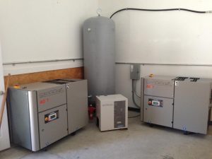
Now compare the package rating with the nozzle demand, simultaneous loads, named allowance, and documented delivery requirement. If units, pressures, or rating conditions differ, leave the mismatch visible until the manufacturer supplies compatible data. Paint Booth’s compressed-air equipment page shows the type of packaged equipment involved, but the exact model still has to satisfy the recorded blasting condition.
Hand the supplier one complete blast-system capacity record
One page is enough for the handoff. Put the nozzle manufacturer and number beside the nominal and measured orifice, selected pressure at the nozzle, and manufacturer demand at both the new and permitted wear-limit conditions. Add blast duration, pauses, and expected hours per shift.
List each air user that runs during blasting, its sourced volume, and the operating allowance with the organization that specified it. Then describe the airline from compressor to blast machine, including treatment components and the location where pressure was observed under flow.
For the existing or proposed compressor, include the exact model, delivered capacity, rating pressure, reference conditions, package boundary, and control basis. A planned nozzle, operator, or shift belongs in a separate future-demand line so it doesn’t disappear into today’s total.
Ask the supplier to return those same assumptions with the proposal. That response makes it easy to spot a new-nozzle value paired with a worn-nozzle operation, a generic helmet load, an undocumented reserve, or capacity quoted at another pressure.
For a cabinet or full sandblasting booth, send the completed record with a Paint Booth quote request. The shop doesn’t need to guess a compressor size before making contact. It needs to show the exact demand the proposed package must sustain.
The answer to “what size compressor?” is therefore a capacity at stated conditions, not a tank size or horsepower label. Begin with the actual nozzle and working pressure, size for the worn orifice allowed in service, add only simultaneous documented loads and a named allowance, then verify delivery through the real airline. A current compressor package that meets that complete requirement is the right size candidate for the job.