
Increasing sandblasting output rarely starts with buying a larger air compressor or pushing an operator to blast faster. Possible bottlenecks include non-blasting cycle delays, inconsistent air pressure at the nozzle, and rework caused by unstable operating parameters.
To increase production without sacrificing surface quality, you must isolate the exact step that restricts accepted parts through the facility, stabilize the process, and measure improvements against a verified baseline.
Measure Accepted Work Through the Complete Cycle
Evaluating blast room efficiency based solely on gross square footage blasted or total parts blasted per shift conceals the real cost of production. If twenty percent of those parts require re-blasting to meet a cleanliness or profile standard, high blast speeds simply generate scrap faster. Efficiency must be measured as accepted parts per shift—work that meets quality criteria on the first pass and moves immediately to downstream coating.
Accurately diagnosing capacity requires mapping a complete, single-part or batch cycle from floor to floor. Track a consistent part geometry across a representative shift using specific operational buckets:
| Cycle Component | What It Captures | Primary Operational Risk |
|---|---|---|
| Staging & Loading | Moving raw parts into the booth, rigging, fixturing, and closing doors. | Crane queues, manual handling friction, improper racking. |
| Pressurization & Setup | Operator PPE donning, blast pot charging, deadman engagement. | Air line leaks, slow pot filling, worn remote valves. |
| Active Blasting | Trigger-on time where media strikes the substrate. | Pressure drop under load, poor media metering, improper standoff. |
| Dust Clearance | Post-blast ventilation dwell before opening doors. | Undersized dust collection, clogged filter cartridges. |
| Unloading & Blow-Off | Clearing residual abrasive from pockets, opening doors, moving parts out. | Poor blow-off tooling, handling delays. |
| Post-Blast Inspection | Verifying cleanliness (SSPC/NACE standards) and surface profile depth. | Lack of clear go/no-go gauges, delayed QA handoff. |
| Rework Time | Re-rigging and re-blasting areas that failed visual or profile checks. | Inconsistent abrasive sizing, operator fatigue, poor lighting. |
| Unscheduled Stoppages | Clearing nozzle clogs, refilling media hoppers, mechanical reclaim jams. | Wet compressed air, trash in media, worn belt/auger components. |
Recording these time intervals across multiple runs of the same part type establishes a verifiable baseline. The data will reveal whether your constraint is physical processing time or systemic operational delay.
Determine Whether the Limit Is Blasting or Waiting
Once cycle times are categorized, calculate the ratio of active blast time against total floor-to-floor time. Use the measured cycle breakdown to identify where time is being spent; there is no universal trigger-time percentage that proves an operation is efficient.
If active blast time dominates the measured cycle and parts still stack up outside the booth, investigate whether the blast process is the constraint. In this scenario, investigate media flow, nozzle sizing, air delivery, and operator technique.
If waiting and handling dominate the measured cycle, investigate those delays before trying to increase blasting speed. Accelerating nozzle velocity will not fix a booth that sits idle while an operator waits for an overhead crane, manually shovels spent grit from dead zones, or clears dust from the room.
When material movement causes the delay, evaluate how the physical sandblasting booth layout manages the flow of unblasted versus finished parts. Dead-end booths often force incoming and outgoing jobs to fight for the same floor space and crane hooks.
Similarly, if part geometries require tedious repositioning, fixturing, or produce severe operator fatigue, investigating automated sandblasting for high-volume, standardized parts may be the long-term solution. However, automation should only be considered after you streamline manual movement and stabilize the underlying process.
Check Process Stability Before Changing Equipment
Never alter blast equipment or room configurations until you have verified that your baseline air, media, and ventilation systems operate within proper parameters. Small mechanical faults compound quickly, creating symptoms that masquerade as capacity deficits.
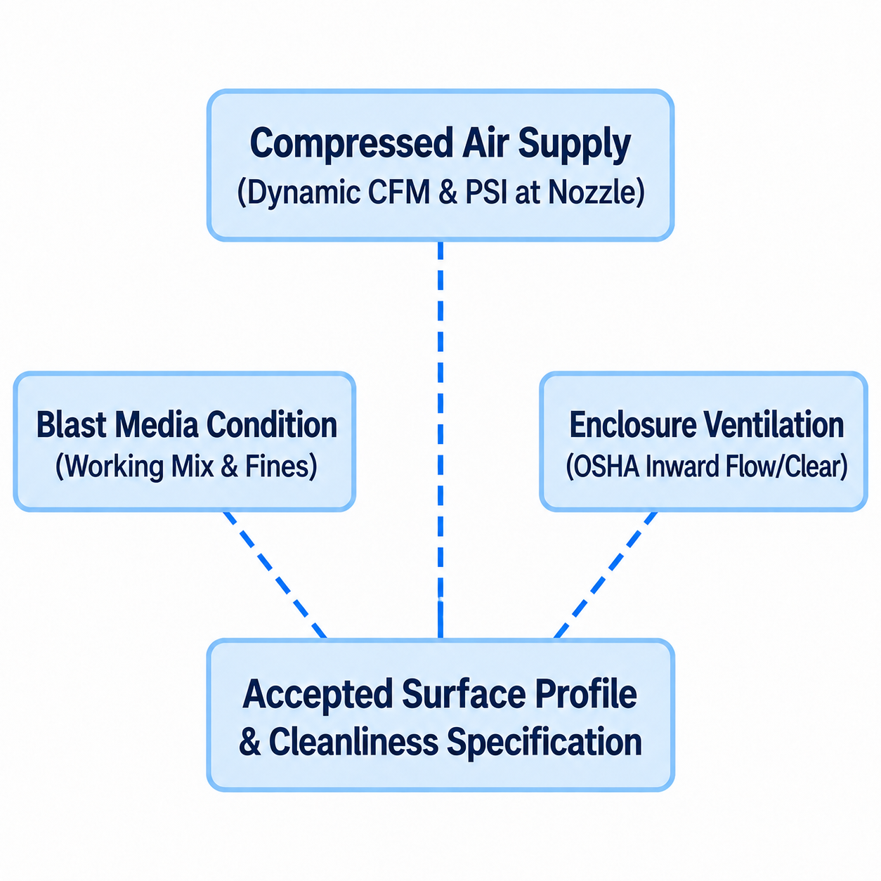
Diagram description
- Compressed Air Supply
- (Dynamic CFM & PSI at Nozzle)
- Blast Media Condition
- (Working Mix & Fines)
- Enclosure Ventilation
- (OSHA Inward Flow/Clear)
- Accepted Surface Profile & Cleanliness Specification
- Compressed Air Supply ⋯ Accepted Surface Profile & Cleanliness Specification; dashed association, independent review context
- Blast Media Condition ⋯ Accepted Surface Profile & Cleanliness Specification; dashed association, independent review context
- Enclosure Ventilation ⋯ Accepted Surface Profile & Cleanliness Specification; dashed association, independent review context
1. Air Supply Under Load
Have trained personnel verify air delivery under load using the exact equipment’s approved measurement procedures. Static receiver pressure alone does not establish pressure available at the nozzle.
Undersized supply lines, restrictive fittings, or excessive filter resistance can reduce pressure available at the nozzle and affect cleaning performance; the effect depends on the system and job. Furthermore, check nozzle orifice wear with a standard nozzle orifice gauge. As nozzles wear, their internal diameter widens, requiring significantly more CFM to maintain target pressure. If your compressor cannot satisfy that higher CFM demand, operating pressure collapses.
2. Machine Integrity and Pneumatic Response
Pneumatic blast controls must engage and exhaust cleanly. The Clemco Classic Blast Machine OM 22501 manual outlines observational checks for identifying wear in remote control lines, pop-up valves, and abrasive metering assemblies.
Air leaks in dual-line control hoses create sluggish pressurization and depressurization cycles, wasting seconds on every start and stop. Air leaks or wet compressed air also lead to erratic media feed: moisture agglomerates abrasive in the metering valve, resulting in choking, surging, and frequent operator shutdowns to clear clogs.
3. Blast Media Quality and Working Mix
A stable process requires a consistent abrasive working mix rather than erratic charges of fresh media alternating with worn-out dust. The blast media condition dictates both cleaning speed and surface profile.
Following the sampling and sieving approach described in Winoa WA-MO operating-mix inspection guidance allows operations using recyclable steel abrasives to verify their working mix. By taking representative samples from the blast line and running them through a calibrated sieve stack, you can confirm whether the abrasive mix maintains the correct balance of large working particles to break scale and smaller particles to provide dense coverage.
If the reclaim system's airwash separator is improperly balanced, it will either discard usable, coarse abrasive into the dust collector or leave fine dust in the mix, blinding the operator and slowing cleaning rates.
4. Ventilation and Enclosure Standards
Under OSHA 1910.94(a), blast enclosures must maintain continuous inward airflow at all openings while blasting is active, and operators must allow sufficient dust clearance time before opening doors. Inward air velocity prevents respirable dust from escaping into surrounding plant areas.
Enclosure ventilation must never be confused with the mechanical abrasive reclaim system. Ventilation moves air to manage visibility and capture suspended particulates; reclaim systems lift, clean, and screen heavy abrasive for reuse. When enclosure airflow declines, visibility can degrade and clearance times can extend, inflating total cycle time. Collector differential pressure measures pressure difference across the filters; interpret it alongside airflow and static-pressure readings at defined system locations.
5. Profile Verification vs. Cleanliness
Blasting faster means nothing if the anchor pattern fails to meet the coating manufacturer’s technical data sheet. Guidance from Elcometer Understanding Surface Profile emphasizes that surface profile depth is an independent variable from visual surface cleanliness (such as SSPC-SP 10 / NACE No. 2).
Visual cleanliness can be achieved with fine media, but fine media may not generate the required peak-to-valley height for coating adhesion. Conversely, running overly coarse grit creates excessively deep profiles with sharp peaks that liquid coatings cannot bridge, causing pinpoint rusting and rejected work. Measure profile systematically on actual production parts using replica tape or surface profile gauges to ensure your blast speed is producing an acceptable substrate.
Test One Improvement Against Quality and Throughput
Once the process is stable and the baseline is documented, implement adjustments in isolation. Altering multiple variables simultaneously—such as changing abrasive size, swapping the nozzle, and revising part staging during the same week—makes it impossible to identify which change caused the resulting performance shift.
Select a single, approved change based on your cycle analysis:
- If pressure drops under load: Have qualified personnel review hose sizing, restrictive fittings, and nozzle wear against OEM requirements before selecting a correction.
- If visibility and dust clearance lag: Arrange qualified evaluation of enclosure airflow and collector condition using OEM and site procedures; assess abrasive separation separately.
- If rework rates are high: Review abrasive condition and operator coverage against qualified process parameters before approving a trial change.
- If loading delays dominate: Review staging and part presentation with qualified handling personnel before approving changes to carts or racking.
Run the test across a controlled batch of identical parts. Measure the outcome strictly against accepted throughput:
True Productivity = (Accepted First-Pass Parts) / (Total Cycle Time (Including Handling and Stoppages))
Track secondary effects as well. Note whether the change increases media consumption per square foot, accelerates nozzle wear, or shifts the bottleneck to another station, such as post-blast masking or prime painting.
Turn Persistent Capacity Limits into Supplier Questions
If you have eliminated air pressure drops, balanced your working mix, cleared non-blast handling delays, and fully stabilized the manual blast cycle, you may reach the physical limit of the machine. At this point, evaluate whether equipment modification or replacement addresses the documented limit.
Take your operational cycle data directly to equipment manufacturers. Rather than asking a generic question about booth sizing, present your documented production profile:
- Part Mix and Physical Envelope: Dimensions, weights, surface conditions (e.g., heavy mill scale, laser oxide, multi-coat paint), and part staging orientations.
- Documented Cycle Breakdown: Your baseline showing active blast trigger time, handling duration, and current dust clearance times.
- Quality Metrics: Required surface cleanliness (SSPC/NACE specifications) and required surface profile depth ranges dictated by your coating systems.
- Facility Constraints: Maximum available compressed air capacity (actual CFM under load), available electrical service, physical floor footprint, and overhead clearance.
This data allows manufacturers to answer precise engineering questions: Will an upgraded reclaim system handle your abrasive circulation rate? Does the ventilation system provide the required inward flow and validated post-blast clearance period? Would an automated blast table, monorail pass-through, or multi-operator pressure pot balance the line?
If your facility is evaluating the capacity, ventilation balance, or material flow of its sandblasting booth equipment, contact PaintBooth to discuss equipment options using your production data and floor space requirements.