
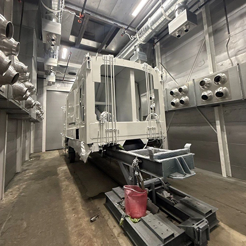
A paint booth's energy efficiency cannot be judged by the efficiency label on its burner or the horsepower rating on its exhaust fan. True operating efficiency is determined by how well the equipment matches its thermal and electrical draw to your actual production schedule. An industrial spray booth moves thousands of cubic feet of air per minute to protect operators and meet safety codes; conditioning and moving that massive volume of air is where utility dollars are spent.
To evaluate competing equipment proposals, buyers must look past nameplate ratings and analyze energy consumption across every phase of their daily cycle: spraying, idling, and curing.
The Energy Balance Across Spray, Idle, and Cure Phases
Energy consumption in a paint booth shifts dramatically depending on the active stage of the finishing process. Evaluating a booth requires breaking down utility demand by phase rather than averaging consumption across a shift.
| Phase | Primary Energy Driver | Operational Objective |
|---|---|---|
| Spray Mode | Design fan load + any required replacement-air conditioning | Maintain specified ventilation and process conditions |
| Idle Mode | Fan and conditioning demand during permitted idle periods | Evaluate compatible OEM modes for the actual workload |
| Cure / Bake Mode | Heating and airflow specified for the selected cure process | Follow coating and equipment requirements for the cycle |
Spray Mode
During active spraying, the booth operates at full process airflow. The system must maintain the ventilation specified for the equipment, coating process, and applicable requirements; a generic cabin-velocity range is not a substitute for that review.
During spray mode, fan electricity and conditioning demand depend on the actual airflow, system resistance, controls, and process conditions. Where outdoor replacement air is heated, the load depends on airflow and the temperature rise required by the process. In colder climates, this can be a major energy demand alongside fan electricity.
Idle Mode
Production bottlenecks, part staging, masking, tack-ragging, and gun flushing mean spray guns are actively atomizing coating for only a fraction of an operational shift. If the booth runs at full exhaust velocity and design temperature while an operator unwraps a part, the system exhausts fully conditioned air straight through the exhaust stack while between production tasks. The amount of idle demand worth addressing depends on your actual operating schedule and the modes the equipment safely supports.
Cure and Bake Mode
For a heated cure process, use the coating data sheet and equipment instructions to establish the cycle. Temperature, ventilation, purge, and access requirements remain equipment- and process-specific; an unoccupied cabin does not by itself permit reduced airflow.
How the equipment handles cure airflow—specifically whether and how it safely recirculates heated air—governs fuel consumption in this phase.
Fan Power and Dynamic Airflow Control
Fans operate under mechanical physical laws, but actual shop utility bills reflect dynamic system resistance rather than idealized math.
| THEORETICAL FAN LAW | REAL-WORLD DUCT SYSTEM |
|---|---|
|
|
Under comparable fan-law conditions, the fan affinity laws relate shaft power to the cube of rotational speed:
(P1) / (P2) = ((N1) / (N2))3
As an illustrative fan-law calculation, reducing speed by 20% gives about 51% of the original shaft power, not a guaranteed reduction in measured electrical consumption. In practice, a paint booth exhaust system does not operate in an ideal laboratory environment. Intake filters and exhaust arrestors continuously load with particulate, increasing static pressure across the system. Ducts, dampers, and weather hoods impose fixed mechanical resistance. A system that maintains the same airflow against greater resistance may require more power; a fixed-speed system may instead lose airflow.
Some compatible systems use variable-speed fan controls to coordinate motor speed with their designed operating modes or feedback controls. Rather than running at full brake horsepower throughout an eight-hour shift, these systems modulate fan RPM to:
- Maintain the specified airflow or balance where the selected system includes suitable feedback control.
- Reduce fan speed during the OEM’s intended non-spraying mode, reducing fan demand and exhausted heated air where that mode is supported.
Global Finishing Solutions (GFS), for instance, documents an Economy Mode that reduces fan speed while the booth is idle and restores airflow when the spray gun is triggered. The reduced idle airflow also lowers heating demand.
However, retrofitting dynamic speed controls onto existing machinery is not a simple plug-and-play task. GFS retrofit guidance explicitly notes that a comprehensive equipment compatibility review is necessary before adding VFDs. Have qualified personnel assess fans, motors, burners, controls, and safety interfaces as a complete system; a VFD alone does not establish safe operation at reduced airflow.
Thermal Systems and Makeup Air
Understanding how an air make-up system works is central to evaluating any paint booth's energy consumption. An air makeup unit (AMU) supplies replacement air; filtration, heating, cooling, delivery arrangement, and pressure balance depend on the selected design.
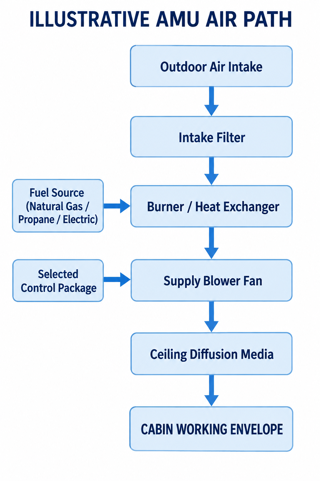
Diagram description
- Outdoor Air Intake
- Intake Filter
- Burner / Heat Exchanger
- Supply Blower Fan
- Ceiling Diffusion Media
- CABIN WORKING ENVELOPE
- Fuel Source (Natural Gas / Propane / Electric)
- Selected Control Package
- Outdoor Air Intake → Intake Filter
- Intake Filter → Burner / Heat Exchanger
- Burner / Heat Exchanger → Supply Blower Fan
- Supply Blower Fan → Ceiling Diffusion Media
- Ceiling Diffusion Media → CABIN WORKING ENVELOPE
- Fuel Source (Natural Gas / Propane / Electric) → Burner / Heat Exchanger
- Selected Control Package → Supply Blower Fan
How that air is heated dictates capital cost, fuel efficiency, and facility venting requirements.
Direct-Fired Gas Burners
In a direct-fired system, the natural gas or propane flame burns directly in the incoming process airstream. Compare the supplier’s rated performance and fuel estimate under your workload rather than treating burner efficiency as whole-booth efficiency.
Combustion products enter the supply airstream in a direct-fired design. Have the selected equipment’s air-quality, ventilation, and operating requirements reviewed for the process; do not infer suitability from a burner label alone.
Indirect-Fired Systems
Indirect-fired units pass combustion gases through an internal heat exchanger; the cabin process air passes over the exterior of the exchanger without contacting the flame or combustion exhaust. The combustion byproducts exit via a dedicated exhaust flue.
The heat exchanger separates combustion gases from the process airstream. Account for exchanger and flue losses when comparing actual proposals, and verify process-air conditions against coating requirements. The heat exchanger also represents an additional component subject to thermal fatigue, crack inspection, and long-term replacement.
Heat Recovery Technologies
Air-to-air heat exchangers and run-around coil loops capture sensible heat from the warm exhaust airstream to preheat cold incoming supply air. Its value depends on climate, operating hours, recoverable heat, and the complete system’s electrical and maintenance demands.
Yet heat recovery introduces engineering trade-offs:
- Assess overspray fouling risks, required filtration, cleaning access, and maintenance costs for the selected recovery design.
- Account for added air-path resistance and the resulting fan-system requirements in the proposal.
- The physical distance between the exhaust stack and the intake AMU can make ducting runs complex and expensive.
Buyers should evaluate heat recovery based on local degree-days and operational hours rather than adopting or dismissing it based purely on shop footprint.
Cure Recirculation Architecture
Some designed cure systems recirculate a portion of heated air to reduce exhausted heat. Evaluate the selected system’s allowed modes, ventilation, and safety controls rather than assuming a modern booth includes recirculation or a particular saving.
Follow the equipment’s documented purge, ventilation, recirculation, and control requirements and the applicable approvals for the coating process. Do not use a generic purge duration or air percentage as an operating instruction. Recirculation rates must never be modified outside OEM and safety code specifications.
Illumination, Visibility, and Rework Economics
Lighting is frequently treated as an afterthought in energy evaluations, yet it plays an interconnected role in overall operational costs. Include any observed rework costs when evaluating lower-wattage lighting; fixture electricity alone does not establish overall value.
When calculating the energy cost of fixing a paint defect: Additional Rework Energy Cost = Additional Prep Energy Cost + Repeated Process Energy Cost
Track the additional preparation and process energy associated with actual rework rather than assuming every correction doubles the original cycle cost.
LIGHTING EFFICIENCY CRITERIA
- Hazardous Location Certification
- Verify listings for the actual location, process, and equipment
- Color Rendering & Finish Visibility
- Evaluate color rendering, light distribution, and task visibility
- Thermal Load to the Cabin
- Include fixture power and any relevant cooling load in the comparison
Upgrading to compatible LED lighting can reduce lighting electricity use compared with the fixtures being replaced. Confirm compatibility, output, and the listings required for the actual installation.
Beyond electrical draw, GFS lighting guidance discusses energy use and visibility. Evaluate fixture output, placement, color characteristics, and compatibility for your actual work surfaces; a color-temperature or CRI value alone does not guarantee shadow-free illumination or finish verification.
Comparing Equipment Proposals Against an Identical Workload
Equipment manufacturers frequently present energy estimates based on ideal assumptions: continuous full-capacity runs, mild ambient outdoor temperatures, or maximum theoretical burner efficiencies. To make an objective investment decision, build a standardized workload baseline and evaluate every proposal against the exact same operating scenario.
Baseline Evaluation Model
For illustration only, consider a production facility with the following operational profile. These figures are comparison inputs, not recommended coating or equipment settings:
- Operating Schedule: 8 hours per day, 250 days per year.
- Throughput: 6 cycles per day.
- Per-Cycle Profile:
- 30 minutes active spraying (70°F setpoint)
- 20 minutes staging/unmasking (idle)
- 30 minutes curing (150°F target)
- Local Climate: Average heating season ambient temperature of 35°F.
| Evaluation Factor | Base Model (Fixed Speed) | Advanced Controlled Model |
|---|---|---|
| Active Spray Exhaust Airflow | 10,000 CFM (Constant) | 10,000 CFM (Constant) |
| Fan Control Architecture | Direct-on-line / Fixed Pulley | Variable-speed fan controls |
| Idle Mode Performance | 10,000 CFM @ 70°F | 6,000 CFM @ 60°F |
| Cure Mode Air Handling | 100% Exhaust @ 150°F | Monitored Recirculation |
| Connected Motor Rating | 15 HP nameplate total | 15 HP nameplate total |
| Lighting Package | T8 Fluorescent (Hazardous Loc) | Compatible LED lighting |
| Fuel Demand (35°F Example Day) | Obtain phase-specific estimate | Obtain phase-specific estimate |
For this illustrative comparison, ask suppliers to quantify any differences under the same workload and confirm that each listed mode is supported:
- Idle Savings: For the illustrated 120 minutes of idle time, compare measured or modeled fan electricity and conditioning demand under the permitted idle mode.
- Cure Savings: Where the selected cure design permits recirculation, account for both enclosure losses and required replacement-air heating, alongside any warm-up demand.
- Electrical Demand: Ask how the selected feedback and fan controls maintain specified airflow as filters load, and request the corresponding electrical-use assumptions.
Evaluating systems against your facility’s real schedule helps compare option costs and expected operating demand without assuming a higher-priced package always delivers better value.
Infrastructure, Site Prep, and Inquiry Specifications
High-efficiency equipment often imposes distinct mechanical and spatial constraints on your building. Reviewing utility requirements before installation avoids expensive change orders during installation.
PRE-INSTALLATION SITE AUDIT
- Gas Supply
- Adequate delivery pressure during design load
- Electrical Service
- Correct ampacity & requirements for selected controls
- Compressed Air & Structural
- Clean, dry air for inter-locks; clearance for straight duct runs
- Gas Service and Metering: A high-capacity burner requires specific minimum inlet pressures and pipe diameters to operate correctly at high firing rates. Have qualified personnel verify fuel delivery under the equipment’s required load rather than assuming current service capacity is sufficient.
- Electrical Supply and Harmonic Mitigation: Variable frequency drives generate electrical harmonics that can interfere with sensitive electronic controls elsewhere in a facility if not planned for. Have qualified electrical personnel verify supply voltage, circuit capacity, grounding, and any required mitigation for the selected drives and controls.
- Exhaust Duct Topography: Review the selected manufacturer’s duct requirements against the proposed site route. Duct resistance affects fan performance; review the actual fan, duct, and control combination to establish airflow and power demand.
- Maintenance Access for Filtration: Confirm the selected air makeup system’s filtration and maintenance requirements. Ensure the booth footprint allows sufficient physical clearance for service personnel to access filter housings and drive belts without obstructing shop operations.
Data to Prepare Before Contacting Manufacturers
When you prepare to request a project quote, provide prospective equipment manufacturers with detailed site and process data. Provide the inputs needed for suppliers or qualified project reviewers to state their fuel and electrical-use assumptions:
- Production Cadence: Target parts per shift, average spray application time per part, and required cure times from your coating technical data sheets (TDS).
- Facility Utilities: Gas type (natural gas or LP), available incoming supply pressure, electrical phase, line voltage, and service panel ampacity.
- Facility Geography: Elevation above sea level (which directly impacts air density and burner sizing) and local outdoor winter/summer design temperatures.
- Coating Specifications: Flash points, volatile organic compound (VOC) content, transfer efficiency, and recommended curing temperatures.
Specifying these operational parameters shifts the conversation away from generic marketing assertions and grounds your procurement process in verifiable performance data.
Sources
- https://globalfinishing.com/2013/04/22/earth-day-energy-saving-5-pieces-of-paint-booth-tech-that-do-more-and-use-less/
- https://globalfinishing.com/2019/05/07/bright-ideas-to-boost-your-paint-booth-lighting/
- https://www.paintbooth.com/how-a-make-up-air-system-works/
- https://www.paintbooth.com/what-utilities-do-you-need-before-installing-a-paint-booth/
- https://www.paintbooth.com/quote/
- https://www.energy.gov/sites/default/files/2014/05/f16/fan_sourcebook.pdf
- https://www.greenheck.com/resources/blog/direct-gas-fired-make-up-air-units-deliver-benefits-safely
- https://www.appliedair.com/ProductTypes/Details/indirect-fired