
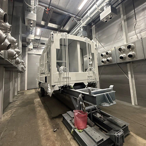
A spray booth is an air-evacuation machine. When an exhaust fan pulls 10,000 cubic feet per minute (CFM) of solvent-laden air out of a booth cabin, that exact volume must be replaced instantly. If a facility does not actively supply that air, the exhaust fan draws it under exterior doors, through wall joints, and down furnace flues, pulling shop dust and unconditioned outdoor drafts into the finishing area.
An Air Make-Up Unit (AMU) resolves this imbalance. It draws fresh outdoor air, filters out particulate matter, heats or tempers the air stream to a target operating temperature, and delivers a controlled volume of air directly into the spray booth or the host facility.
The Path of Replacement Air: From Intake to Cabin
The physical journey of replacement air begins well outside the building envelope and ends at the booth exhaust stack. Every transition point along that path protects either the finish quality, the equipment, or operator safety.
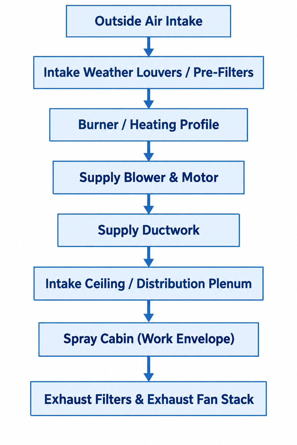
Diagram description
- Outside Air Intake
- Intake Weather Louvers / Pre-Filters
- Burner / Heating Profile
- Supply Blower & Motor
- Supply Ductwork
- Intake Ceiling / Distribution Plenum
- Spray Cabin (Work Envelope)
- Exhaust Filters & Exhaust Fan Stack
- Outside Air Intake → Intake Weather Louvers / Pre-Filters
- Intake Weather Louvers / Pre-Filters → Burner / Heating Profile
- Burner / Heating Profile → Supply Blower & Motor
- Supply Blower & Motor → Supply Ductwork
- Supply Ductwork → Intake Ceiling / Distribution Plenum
- Intake Ceiling / Distribution Plenum → Spray Cabin (Work Envelope)
- Spray Cabin (Work Envelope) → Exhaust Filters & Exhaust Fan Stack
- One vertical downward chain in order: Outside Air Intake; Intake Weather Louvers / Pre-Filters; Burner / Heating Profile; Supply Blower & Motor; Supply Ductwork; Intake Ceiling / Distribution Plenum; Spray Cabin (Work Envelope); Exhaust Filters & Exhaust Fan Stack.
1. Intake Siting and Louvers
The process starts at the outdoor intake hood. Under OSHA 1910.94(c)(7)(i), industrial spray finishing installations require clean replacement air that is free from contamination by adjacent exhaust sources.
Intake louvers must be situated away from:
- Spray booth exhaust stacks
- Building heating flues and boiler vents
- Vehicle loading docks and diesel idling lanes
- Dumpsters and process chemical exhausts
Weather louvers and bird screens catch rain, snow, and large airborne debris before the air contacts the filtration media.
2. Primary Filtration
Air pulled through the intake enters an intake filter bank. These pre-filters—selected for the unit and process—capture airborne road dust, organic matter, and industrial fallout. Removing coarse particles at this stage protects the supply blower fan blades and prevents fouling on the burner profile or heating elements.
3. Supply Blower
The supply blower (typically an industrial centrifugal or direct-drive backward-inclined fan) overcomes the total external static pressure of the intake hood, dampers, ductwork, burner assembly, and ceiling filtration arrays. It mechanically pushes the conditioned air stream downstream into the booth cabin.
4. Cabin Discharge Plenum
In a pressurized booth, the supply duct delivers air into an overhead intake plenum. This plenum contains fine diffusion filters that run across the ceiling. These ceiling filters perform two jobs: they capture finer particles according to their specified efficiency, and they evenly distribute air velocity across the cross-section of the cabin.
In non-pressurized or open-face booths, the AMU discharges conditioned air into the shop space directly surrounding the booth intake face, allowing the booth's exhaust fan to draw in tempered, filtered room air.
How Filtration, Heating, and Airflow Controls Coordinate
A functioning AMU is not merely an air pump; it is a synchronized thermal and aerodynamic system. Inside the mechanical housing, filters, heater, blower and controls work together to manage cabin conditions as outdoor temperatures change and filters load.
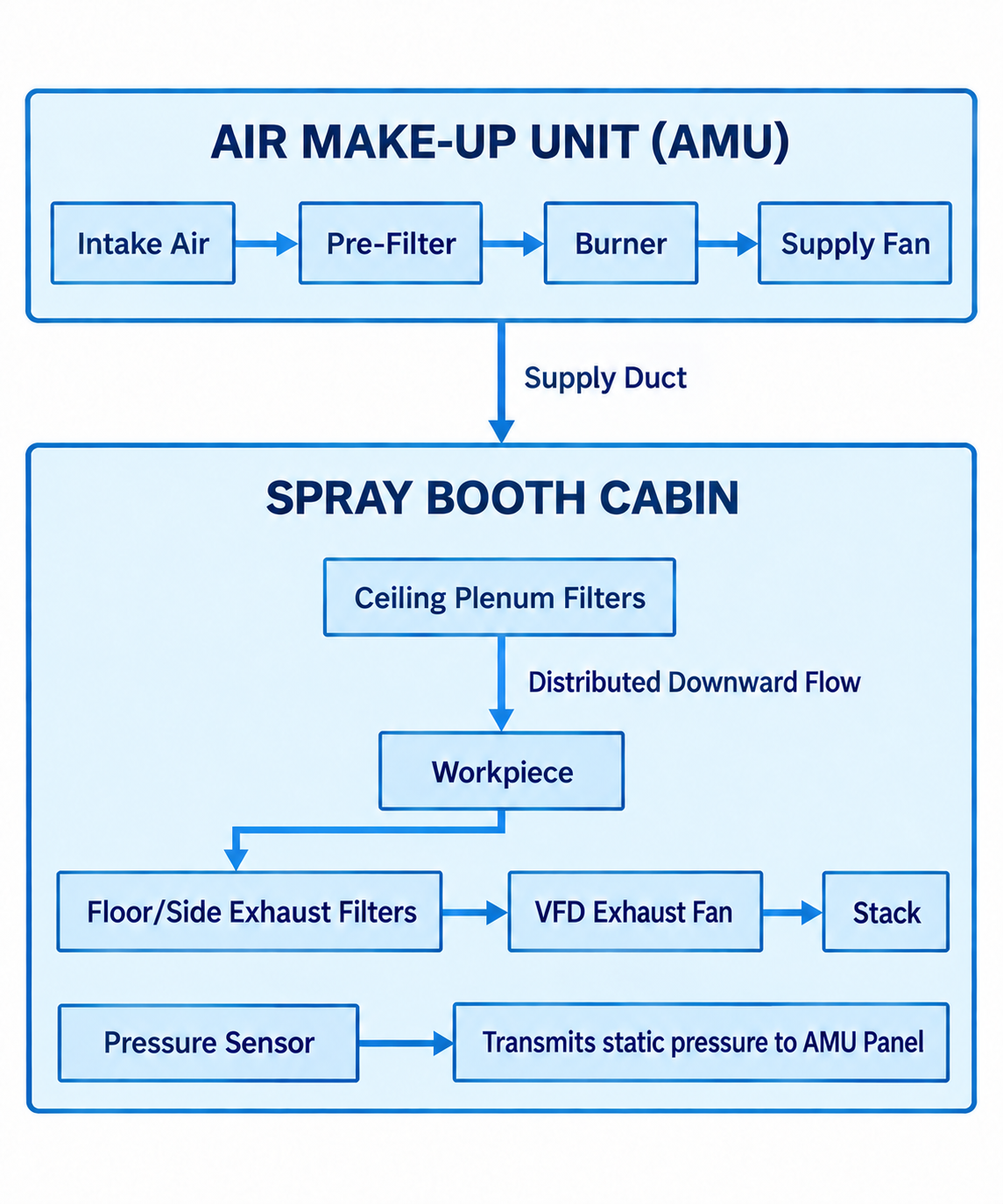
Diagram description
- AIR MAKE-UP UNIT (AMU)
- Intake Air
- Pre-Filter
- Burner
- Supply Fan
- Supply Duct
- SPRAY BOOTH CABIN
- Ceiling Plenum Filters
- Distributed Downward Flow
- Workpiece
- Floor/Side Exhaust Filters
- VFD Exhaust Fan
- Stack
- Pressure Sensor
- Transmits static pressure to AMU Panel
- Intake Air → Pre-Filter
- Pre-Filter → Burner
- Burner → Supply Fan
- AIR MAKE-UP UNIT (AMU) → SPRAY BOOTH CABIN: Supply Duct
- Ceiling Plenum Filters → Workpiece: Distributed Downward Flow
- Workpiece → Floor/Side Exhaust Filters
- Floor/Side Exhaust Filters → VFD Exhaust Fan
- VFD Exhaust Fan → Stack
- Pressure Sensor → Transmits static pressure to AMU Panel
- AIR MAKE-UP UNIT (AMU)
- Intake Air
- Pre-Filter
- Burner
- Supply Fan
- SPRAY BOOTH CABIN
- Ceiling Plenum Filters
- Workpiece
- Floor/Side Exhaust Filters
- VFD Exhaust Fan
- Stack
- Pressure Sensor
- Transmits static pressure to AMU Panel
- AMU outer container contains Intake Air → Pre-Filter → Burner → Supply Fan.
- AMU bottom connection labelled Supply Duct points downward into SPRAY BOOTH CABIN container.
- Cabin contains Ceiling Plenum Filters → downward Workpiece (arrow qualifier Distributed Downward Flow) → downward Floor/Side Exhaust Filters → VFD Exhaust Fan → Stack.
- Separate Pressure Sensor → Transmits static pressure to AMU Panel inside cabin.
Direct-Fired vs. Indirect-Fired Heating
To prevent flash-off defects, pinholing, or blushing, liquid coatings require stable application temperatures within the coating supplier’s specified range. AMUs supply this heat through one of two burner configurations:
- Direct-Fired Gas Burners: The raw outside air stream flows directly across an open burner flame fueled by natural gas or propane. Direct-fired burners transfer combustion heat directly into the supply air stream. Combustion adds water vapor and other combustion products; burner design, operation, and applicable requirements govern their acceptable levels.
- Indirect-Fired Heat Exchangers: The combustion flame remains sealed inside a stainless steel heat exchanger. Outside air passes over the exterior of the hot heat exchanger tubes, picking up heat without coming into contact with combustion products. While less fuel-efficient than direct-fired systems because some heat leaves with the combustion exhaust, indirect units are selected when local codes, specific utility setups, or sensitive processes prohibit direct contact with combustion byproducts.
The Distinction Between Heating and Humidity Control
A common misconception is that standard heating provides humidity control. Heating without adding or removing moisture lowers relative humidity, but does not dehumidify the air. A direct-fired gas burner also adds combustion moisture. Conversely, on hot, humid summer days, heating alone will not remove excess moisture.
When finishing with advanced waterborne coatings, the coating supplier may specify a relative humidity window for predictable evaporation rates. Shops evaluating air makeup unit options must recognize that true moisture regulation requires specialized sub-systems:
- Humidification: May use a suitably designed steam or atomizing system.
- Dehumidification: May use DX (direct expansion) or chilled-water coils to condense moisture, or desiccants to remove moisture by sorption; any reheating is part of the selected design.
Pressure Management and Variable Frequency Drives (VFDs)
As overspray loads onto booth exhaust filters, resistance (static pressure) across the exhaust system increases. If fan settings are unchanged, this increased resistance throws the booth out of balance.
Some AMU control panels use differential pressure transducers to continuously read cabin static pressure relative to the host building. The panel modulates a Variable Frequency Drive (VFD) on the exhaust fan, supply blower, or both. The control response and pressure target depend on the manufacturer’s configured supply, exhaust, and damper arrangement.
A suitably balanced pressurized booth can reduce infiltration of unconditioned shop dust.
Airflow and Damper Transitions: Spray Mode vs. Cure Mode
An AMU’s operating modes depend on its design. Cure-capable systems may change airflow or its path between paint application and accelerated drying; a standard replacement-air unit does not automatically provide these functions.
| Parameter | Spray Mode | Cure / Bake Mode |
|---|---|---|
| Air Source | 100% Outdoor Air (Single-Pass) | Outdoor air, or designed cure-only recirculation |
| Airflow Volume | 100% Design CFM | Manufacturer-specified airflow for the cure process |
| Cabin Temperature | Coating-specified application setpoint | Elevated curing setpoint (per coating specifications) |
| Damper Profile | Designed single-pass supply and exhaust path | Design-specific outdoor-air or recirculation path |
| Primary Safety Concern | Solvent vapor dilution below LFL | Overheating, volatile accumulation, interlock compliance |
Spray Mode: Total Evacuation
During active application, the AMU runs on a single-pass cycle: 100% outside air is brought in, filtered, heated to application setpoint, pushed through the cabin, and exhausted outdoors.
For conventional liquid spray booths, OSHA 1910.107 requires exhaust to discharge outdoors rather than recirculate. Spray hazards and any specialized arrangements must be reviewed against the applicable requirements. Mechanical ventilation must be designed and operated to control flammable vapors, remove mists to a safe location, and confine combustible residues; continuous operation alone does not establish safe concentrations.
Cure Mode: Recirculation and Energy Reduction
A cure-capable system follows its designed transition and ventilation sequence after spraying stops. Heating a large outdoor-air volume to bake temperature can be a substantial energy load.
In installations designed for cure-only recirculation:
- The designed damper arrangement routes a specified portion of cabin air back through the heating section.
- The AMU adds enough heat to raise the air to the coating manufacturer's specified cure temperature.
- A mandatory volume of fresh outdoor air continues to enter the system, and a matching volume exhausts through the roof. The required ventilation must be validated for the coating’s off-gassing and the equipment design.
- Some designed force-dry systems instead use outdoor air throughout and reduce airflow during cure; confirm the available mode with the manufacturer.
Mechanical and Electrical Interlocks
OSHA and NFPA standards mandate that ventilation and drying controls be mechanically and electrically interlocked. The supplier must identify how its burner and ventilation airflow are proved and interlocked for each operating mode.
Similarly, the spray equipment (pneumatic air drops or electrostatic power supplies) is interlocked with the ventilation controls. The supplier must explain how loss of required ventilation prevents spraying and how any drying-mode transition is controlled.
Engineering an AMU: Data Your Equipment Supplier Needs
Because an AMU must counter outdoor climatic extremes while matching the fluid dynamics of an exhaust stack, it cannot be purchased "off the shelf" without engineering validation.
When preparing an equipment brief or reviewing site readiness, compile the following facility and process parameters:
SUPPLIER INTEGRATION CHECKLIST
- Facility Aerodynamics
- ☐ Exhaust CFM & Static Loss
- ☐ Cabin Dimensions & Style
- ☐ Concurrent Shop Exhausts
- ☐ Physical Intake Clearance
- ☐ Roof Structural Capacity
- ☐ Pressurized or Direct Open
- Thermal & Utility Parameters
- ☐ Winter Design Temp (ASHRAE)
- ☐ Target Delta-T (Temp Rise)
- ☐ Fuel Source: Natural Gas/LP
- ☐ Gas Pressure (Inches WC/PSI)
- ☐ Electrical Voltage & Phase
- ☐ Coating Cure Thresholds
1. Exhaust Dynamics and Cabin Design
- Total Exhaust CFM: Sourced from the exhaust fan nameplate or certified performance curve, calculated at the actual static pressure of your exhaust duct run.
- Booth Airflow Style: Crossdraft, side-down, or full downdraft. Required airflow depends on the work-zone geometry and the selected ventilation design.
- Envelope Relationship: State clearly whether the AMU will connect directly to a sealed, pressurized booth plenum via dedicated ductwork or discharge into an open shop space to feed non-pressurized booths.
2. Host Building Aerodynamics
- Concurrent Exhaust Loads: Account for other equipment operating in the building envelope—weld smoke collectors, plasma cutting tables, parts washers, bake ovens, and building HVAC exhaust. If your plant exhausts 40,000 CFM across all departments but only supplies 20,000 CFM through standard HVAC, review the net supply and exhaust effect of the proposed booth and AMU together.
3. Geographical Climate Extremes
- Winter Design Temperature: Sizing a burner requires the outdoor design temperature selected by the supplier for your location and process. Heating 12,000 CFM of outdoor air from 45°F up to 70°F requires substantially fewer BTUs than heating that same volume from -15°F in a northern climate. This calculated difference is your required Temperature Rise ($\Delta T$).
- Summer Heat and Humidity: If high ambient summer temperatures or high humidity compromise your finish window, discuss temperature- and humidity-controlled air makeup systems with your manufacturer. Ask which cooling or moisture-control options suit the specified finish window.
4. Utility Specifications at the Machine Location
- Fuel Type and Pressure: Specify natural gas or propane (LP). For gas-fired units, supply line diameter and dynamic supply pressure (measured in inches of water column or PSI during full facility operation) dictate burner choices. The supplier must confirm the required gas pressure and protective response to an inadequate supply.
- Electrical Service: Confirm supply voltage, phase, and available panel amperage (e.g., 208V, 230V, or 460V / 3-phase).
5. Commissioning Requirements
When planning integration, establish with your supplier how the system will be commissioned. Confirm responsibility for air balancing, burner setup, safety-control verification, and documented handoff against the manufacturer’s requirements.
Collecting these operational parameters ahead of time allows application engineers to model burner BTU capacities, select proper fan blade profiles, and deliver an AMU that integrates seamlessly with your finishing process. When you are ready to detail your facility parameters and match an air system to your production volume, contact an equipment specialist to request an equipment quote.