
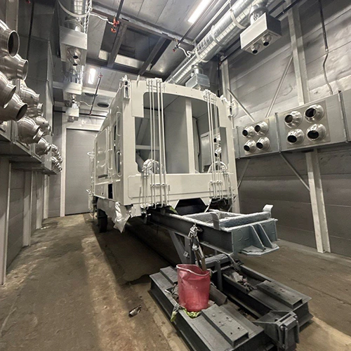
Optimal airflow in a production paint booth is not a static number copied from a textbook. It is a specific operating state established during design and commissioning, engineered to keep airborne overspray moving away from the painter and the workpiece while maintaining safe enclosure conditions.
For a booth manager, preserving that airflow does not mean continually hunting for a universal target velocity across different models and airflow configurations. Instead, it requires establishing a booth-specific baseline, keeping the mechanical airpath unobstructed, accounting for facility-level pressure dynamics, and knowing when to trigger qualified re-verification rather than making guesswork adjustments.
Establish the Booth-Specific Operating Baseline
Airflow verification begins with your equipment’s design specifications, not a generic rule of thumb. A crossdraft booth moving air horizontally down the cabin operates under different velocity and volumetric profiles than a vertical downdraft booth pulling air through a grated pit.
When your booth was installed and commissioned, the engineering data set specific operational targets: total exhaust volume in cubic feet per minute (CFM), target average linear velocity across the cross-sectional working zone, and design static pressures for the cabin and plenums. In the United States, OSHA’s maintained-ventilation requirements under 29 CFR 1910.107 mandate that mechanical ventilation must reliably dilute and evacuate flammable or combustible vapors and overspray during application. However, OSHA does not mandate a single, universal linear velocity for every enclosure geometry; applicable OSHA velocity provisions, the approved design requirements, and other governing requirements must all be assessed.
To manage airflow effectively, you must distinguish between the three distinct measurements reported by gauges and test instruments:
| Measurement Type | What It Measures | What It Does Not Indicate | Typical Instrument |
|---|---|---|---|
| Airflow Velocity | Linear speed of air across the working zone (feet per minute, FPM). | Filter loading status or enclosure structural balance. | Calibrated hot-wire or vane anemometer across a multi-point grid. |
| Filter Differential Pressure | Resistance across an intake or exhaust filter bank (inches water column, in. w.c.). | Actual air speed in the cabin or total exhaust CFM. | Differential pressure gauge / inclined manometer across filter banks. |
| Cabin Static Pressure | Pressure differential between the interior booth cabin and the surrounding shop floor. | Cleanliness of particulate filters or linear flow uniformity. | Static pressure gauge referencing the booth cabin to the exterior room. |
A differential pressure gauge across an exhaust filter bank reports pressure drop at the current flow and sensing arrangement. It does not prove that velocity across the booth face remains uniform, nor does it indicate whether air is bypassing the media through an unseated frame.
Furthermore, your baseline must reflect operating mode. A pressurized downdraft booth running in spray mode demands a different volumetric balance than the same booth operating in cure, bake, or low-volume idle modes. Comparing a static pressure gauge reading taken during cure recirculation to a baseline established during full spray exhaust produces misleading diagnostics. Record baseline values for every discrete operating mode under clean-filter conditions.
Keep the Designed Airpath Intact
Airflow distribution responds to resistance throughout the cabin and its supply and exhaust paths. When physical media shift, plenums collect debris, or parts are staged incorrectly, airflow vectors skew immediately, producing dead zones and overspray roll-back regardless of fan power.
Intake and exhaust media must fit tightly within their holding frames without gaps, sagging, or bypass. In accordance with GFS’s filter-fit and maintenance guidance, exhaust arrestors and intake diffusion media must be installed with structural integrity across every track, ensuring no unfiltered air bypasses the media perimeter.
Dry particulate filters perform a single job: capturing liquid overspray droplets and solid particulate. They do not remove solvent vapors. Ventilation must carry vapors to the intended safe discharge; particulate arrestors do not supply vapor removal. If media are installed loosely, overspray bypasses the filters, coats the exhaust fan blades and ductwork, unbalances the impeller, and progressively degrades airflow volume over time.
To protect the physical airpath:
- Eliminate bypass paths: Gaps between filter pads, crushed frame edges, or loose blanket media allow high-velocity channels of dirty air to bypass filtration, loading exhaust ductwork and throwing off balance.
- Keep distribution plenums clear: Floor pits, subterranean exhaust trenches, and upper intake plenums must remain clean of heavy sediment, standing water, and settled particulate that constrict cross-sectional flow.
- Respect floor grating and return pathways: Never lay plywood, cardboard, or non-permeable protective sheets over exhaust floor gratings or side-wall extraction panels to keep them clean. Choking the return path increases plenum static pressure, reduces linear velocity at the workpiece, and forces turbulence into the spray zone.
- Load workpieces within design limits: Oversized parts positioned directly against exhaust banks act as solid dams. They force air to accelerate violently over the top and sides of the part while creating a stagnant, low-pressure pocket on the operator side. Stage work to allow uniform, continuous clearance between parts, walls, and extraction points.
- Prohibit unauthorized enclosure alterations: Never cut unauthorized access holes, seal off intake ceiling segments to direct air to one corner, or modify factory baffles without engineering approval.
Account for Replacement Air and Building Dynamics
A paint booth exhaust system cannot push air out of the building if replacement air cannot enter it. Restricted replacement air can reduce delivered exhaust flow and alter cabin or building pressure; motor-load response depends on the fan and control system.
Where installed, your air makeup units must provide their designed supply. Their heating, cooling, filtration, and volume-control functions depend on the specific equipment. If an air makeup unit's intake pre-filters load with outdoor dust, its supply belts slip, or its airflow dampers move out of their specified positions, the intake volume drops. The exhaust fan will then attempt to pull air from any available gap—drawing shop dust through door seals, conveyor openings, or floor joints.
Your booth also interacts with overall plant air balance. If your facility adds large structural exhaust systems nearby—such as high-volume welding fume extraction, CNC coolant mist collectors, or burn-off ovens—those systems compete for available air.
Watch for classic air-balance warning signs across the shop-to-booth boundary:
- Personnel doors that resist opening or violently slam shut when unlatched.
- Whistling or high-pitch drafts around door gaskets, unsealed wall penetrations, and light fixture bezels.
- Significant airflow reversals when plant bay doors or roll-up shipping doors open during cold weather.
- Dust inclusion along the perimeter of finished work that tracks with plant shift changes or exterior door cycles.
Airflow problems attributed to booth exhaust fans are frequently building-pressure problems in disguise. Keep seasonal records of facility conditions alongside your equipment baseline to identify whether air starvation originates inside the cabin or out on the shop floor.
Trend Observations and Trigger Qualified Verification
Preserving airflow requires catching system drift before it damages a finish or triggers an airflow fault switch. Waiting for an interlocked differential pressure switch to trip the spray guns means operating conditions have already strayed far from the baseline.
Log gauge readings systematically at standard intervals—ideally at the start of each production shift under identical conditions (same operating mode, booth empty, booth doors latched). Maintain clean, continuous filter inspection records that note differential pressures across both intake and exhaust banks.
Trend readings against the verified baseline for the actual controls and conditions; filter loading can increase differential pressure, while cabin pressure may also change. Sudden deviations from this curve indicate immediate mechanical or operational changes:
- Compare gauge readings with the verified baseline under the same operating conditions.
- Record readings and other observations; remaining near baseline alone does not authorize spraying through a safety fault.
- Escalate sudden changes for qualified review of media condition, sensing connections, airflow distribution, drives, and controls.
- Stop spraying if an operating limit is exceeded, an airflow safety fault activates, or containment is lost; follow the approved shutdown procedure.
A manometer indicates filter resistance, but it cannot verify velocity distribution across the cabin. That requires qualified measurement.
Trigger a professional verification when:
- Baseline differential pressure no longer correlates with predictable media loading cycles.
- The booth cabin experiences chronic over-pressurization or under-pressurization outside its documented baseline; operators should not improvise air makeup adjustments.
- Finish inspections reveal localized dirt drift or inconsistent clearcoat flash times across different zones of the cabin.
- The system undergoes scheduled audit intervals specified by your company's risk management program or local jurisdictional requirements.
Qualified verification should be performed by an industrial ventilation technician or qualified service provider using calibrated diagnostic tools. The technician should perform a multi-point anemometer grid traverse across the working envelope to document average linear velocity and uniformity, measure pressure and airflow in the applicable locations using appropriate instruments, and test fan motor amperage against rated full-load amps (FLA). Interpret these measurements against documented design and applicable requirements; a single measurement set does not establish complete code compliance.
Recheck Airflow After Maintenance and Process Changes
Airflow patterns do not remain static across maintenance interventions or production modifications. Whenever the physical booth or the materials passing through it change, verify the airpath before resuming high-volume production.
Filter Replacements
Replacing exhaust or intake media resets resistance, shifting operating points on the fan curve. Always use media specified by the booth manufacturer or a documented compatible alternative approved for the system. Installing a higher-efficiency exhaust media without checking fan capacity can choke airflow, while a low-efficiency substitute may protect airflow initially while coating the downstream exhaust blower in paint mist. Record initial differential pressure immediately after loading new filters to establish the new starting point.
Mechanical Repairs and Drive Adjustments
Drive work can affect airflow and should receive the specified post-service verification. Follow the belt and drive manufacturer’s run-in and tension-check instructions rather than a universal 48-hour interval.
Coating Chemistry and Application Changes
Transitioning from solventborne primers to high-solids clears, waterborne bases, or plural-component coatings alters overspray loading rates and flash characteristics. Higher-solids materials often load exhaust media faster, causing rapid differential pressure climbs that shorten filter lifecycles. Ensure maintenance schedules adapt to the new chemistry’s loading profile.
Part Staging and Rack Reconfigurations
Altering parts hanging configurations, introducing larger carrier carts, or running tall, flat panels broadside to the airflow changes cabin turbulence. Re-evaluate part layout to confirm clearance around the perimeter and maintain clear paths to the extraction zones.
Control Discipline
Train booth operators to recognize airflow drift and report it immediately through formal channels. Forbid unauthorized field compensations—such as wedging access doors open, taping intake sections, modifying exhaust damper linkages, or manipulating variable frequency drive (VFD) limits without authorized baseline procedures. Improvised adjustments to mask an airflow drop merely hide developing mechanical failures and compromise the operating safety envelope.
When ongoing balance fluctuations or persistent draft issues cannot be traced to normal filter loading, talk with a finishing systems specialist. Be prepared to share your booth model, commissioning baseline numbers, current gauge readings across all modes, and recent facility changes to support an equipment-specific follow-up.