
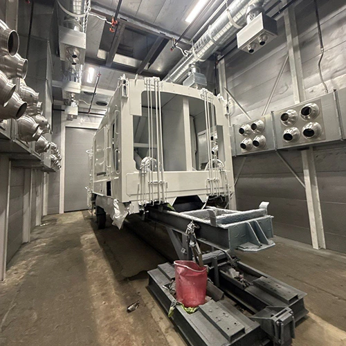
A measured temperature on your control panel reflects the associated sensor location; a displayed setpoint is the intended target. Neither alone establishes the temperature throughout the cabin or on the part. When clearcoat flashes unevenly, bake cycles leave tacky spots on lower rocker panels, or finishes develop unexplained texture, assuming the burner is broken usually leads to wasted downtime.
Diagnosing thermal issues requires separating what the control panel sees from what the cabin air delivers and what the painted substrate absorbs.
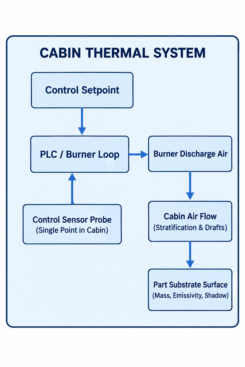
Diagram description
- CABIN THERMAL SYSTEM
- Control Setpoint
- PLC / Burner Loop
- Burner Discharge Air
- Control Sensor Probe
- (Single Point in Cabin)
- (Single Point in Cabin)
- Cabin Air Flow
- (Stratification & Drafts)
- (Stratification & Drafts)
- Part Substrate Surface
- (Mass, Emissivity, Shadow)
- (Mass, Emissivity, Shadow)
- Control Setpoint → PLC / Burner Loop
- PLC / Burner Loop → Burner Discharge Air
- Burner Discharge Air → Cabin Air Flow
- Cabin Air Flow → Part Substrate Surface
- Control Sensor Probe → PLC / Burner Loop
- CABIN THERMAL SYSTEM
- Control Setpoint
- PLC / Burner Loop
- Burner Discharge Air
- Control Sensor Probe
- (Single Point in Cabin)
- Cabin Air Flow
- (Stratification & Drafts)
- Part Substrate Surface
- (Mass, Emissivity, Shadow)
- CABIN THERMAL SYSTEM contains all nodes
- Control Setpoint → PLC / Burner Loop → Burner Discharge Air
- Control Sensor Probe (Single Point in Cabin) upward arrow to PLC / Burner Loop
- Burner Discharge Air → Cabin Air Flow (Stratification & Drafts) → Part Substrate Surface (Mass, Emissivity, Shadow)
- No arrow from substrate or cabin flow to sensor
Classifying Cabin Thermal Discrepancies
Cabin thermal problems fall into four distinct categories. Treating them interchangeably leads to misplaced burner repairs when the root cause lies in airflow or sensing:
| Problem Category | Observable Pattern | Common Underlying Driver |
|---|---|---|
| Spatial Imbalance | Cabin front-to-back or ceiling- to-floor temperature splits | Filter loading, unbalanced exhaust, duct damper drift |
| Cycle Drift | Temperature slowly drops or climbs across a 30-minute cycle | Thermal mass heat-sink, burner modulation hunting, dirty probe |
| Setpoint Failure | Burner fires continuously but cabin never hits bake temperature | Insufficient gas supply, profile plate misalignment, air overload |
| Measurement Disagreement | Panel display says 140°F, but surface pyrometer reads 115°F | IR reading wrong emissivity, probe located in dead-air pocket |
Air Temperature vs. Surface Temperature vs. Setpoint
The control panel displays the process setpoint and the air temperature read by its local resistance temperature detector (RTD) or thermocouple. This value does not reflect the temperature of the vehicle panel or industrial part sitting inside the air stream.
Heavy steel frames, thick castings, and composite panels absorb heat at drastically different rates. Air can sweep across a vehicle roof at 140°F for ten minutes while the lower rocker panel or rear frame rail remains at 110°F. If finish defects occur, consult the paint manufacturer's orange peel guidance and technical data sheets to determine whether fluid delivery, solvent selection, or cabin air speed caused the defect before recalibrating the cabin burner.
The Limits of Infrared Thermometers
Infrared (IR) pyrometers and thermal cameras measure thermal radiation emitted from a solid surface. An infrared thermometer cannot measure air temperature.
Aiming an IR gun into the open air of a paint booth simply measures whatever solid boundary lies in the background—the exhaust wall, a filter face, or the floor grating. Furthermore, bare aluminum, fresh metallic basecoats, and dark e-coats have radically different emissivity ratings. An uncalibrated IR tool aimed at shiny metal reflects background booth temperatures rather than the actual panel temperature, producing false data.
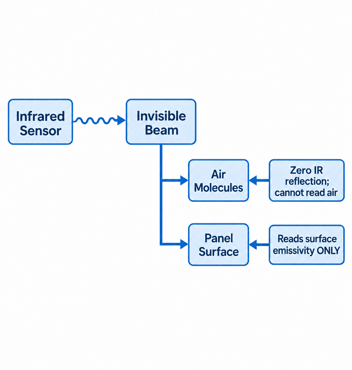
Diagram description
- Infrared Sensor
- Invisible Beam
- Air Molecules
- Zero IR reflection; cannot read air
- Panel Surface
- Reads surface emissivity ONLY
- Infrared Sensor → Invisible Beam: Invisible Beam
- Invisible Beam → Air Molecules
- Invisible Beam → Panel Surface
- Zero IR reflection; cannot read air → Air Molecules
- Reads surface emissivity ONLY → Panel Surface
- Infrared Sensor emits wavy rightward beam to Invisible Beam.
- Beam branches right/down to Air Molecules and separately Panel Surface.
- Air Molecules receives left-pointing annotation Zero IR reflection; cannot read air.
- Panel Surface receives left-pointing annotation Reads surface emissivity ONLY.
Establishing a Comparable Thermal Observation Log
Technicians cannot troubleshoot intermittent or spatial issues using vague reports like "the back corner feels cold." System diagnostics require structured observations taken at identical cycle intervals under known operating states.
| Date & ID | Mode Stage | Elapsed Time | Location In Cabin | Setpoint Temp (Panel) | Sensor Display (Panel) | Substrate Surface Temp (Measured) | Instrument ID / Tool Type |
|---|---|---|---|---|---|---|---|
| 10/12 | Cure | 10 min | Front LH | 140°F | 138°F | 122°F | Type-K Contact #2 |
| 10/12 | Cure | 10 min | Rear RH | 140°F | 138°F | 104°F | Type-K Contact #2 |
| 10/12 | Cure | 20 min | Front LH | 140°F | 141°F | 139°F | Type-K Contact #2 |
| 10/12 | Cure | 20 min | Rear RH | 140°F | 141°F | 121°F | Type-K Contact #2 |
Logging Protocol
To build a reliable diagnostic profile, capture operational context alongside raw numbers:
- Operating Mode: Record whether the system is in Spray, Flash Off, Cure, or Recirculation. Temperature targets, damper alignments, and air velocities shift dramatically between modes.
- Elapsed Time: Note the precise timestamp within the cycle (e.g., 5 minutes after bake ramp-up begins vs. 2 minutes before cool-down).
- Load Mass and Position: Track what is in the booth. Load geometry and thermal mass can affect temperature patterns; record whether the cabin is empty or holds a vehicle or other part.
- Door and Envelope Activity: Note recent personnel-door or vehicle-door activity and its timing relative to the reading.
- Tool Identification: Record the specific instrument used. Have qualified personnel select suitable instruments and distinguish surface-temperature measurements from air-temperature and airflow measurements.
Operational Safety During Thermal Mapping
Never place personnel inside a paint booth cabin during high-temperature cure or bake cycles.
Surface and spatial temperature mapping during heated cycles requires a qualified, site-authorized measurement plan. Instrument ratings, sensor attachment, access points and data collection must suit the installed equipment without impairing door seals, enclosure integrity or safety functions. Ordinary inspection glass is not automatically suitable for infrared measurements; confirm the instrument and viewing-window compatibility.
Do not mount test instruments directly over burner discharge plenums, inside exhaust ductwork, or in hazardous vapor zones where non-intrinsically safe electronics present an ignition risk.
Investigating Mechanical and Sensing Systems
When logs reveal persistent spatial splits or cycle drift, investigate air delivery, burner output, and control loops as independent operational tiers.
Cabin Temperature Imbalance Detected
- Air Delivery
- Filter loading
- Exhaust balance
- Plenum dampers
- Door perimeter
- Thermal Delivery
- Burner modulation
- Gas manifold drop
- Intake preheat
- Recirc damper
- Sensing & Control
- Probe calibration
- Probe wash/shadow
- PID loop drift
- Electrical noise
Air Delivery and Static Pressure Distribution
Heated air carries thermal energy into the workspace. If the air does not move uniformly, heat will not distribute uniformly.
- Intake Ceiling Loading: Unevenly loaded ceiling diffusion media forces warm supply air toward path-of-least-resistance zones, leaving other sections stagnant. Inspect intake and exhaust media according to the manufacturer maintenance instructions; visible loading alone does not establish airflow balance.
- Exhaust Pit Restrictions: Paint overspray building up on floor gratings or loaded exhaust arrestors restricts localized discharge. A starved exhaust zone stalls air movement above it, dropping local convective heat transfer.
- Cabin Air Balance: Verify that exhaust and intake balances comply with published paint booth ventilation requirements. Excessive negative pressure draws cold shop air under door sweep seals and perimeter joints, creating localized cold floors that undermine cure cycles.
Heating Plant and Fresh Air Supply
A burner that operates correctly during low-demand spray cycles may stumble when asked to deliver high-temperature bake air, especially when outside ambient conditions drop.
Understanding how a make-up air system works helps operators separate burner modulation faults from volume delivery problems. Direct-fired make-up air units modulate burner flame output based on a discharge sensor.
Depending on the installed heating system, air-delivery or burner-control faults may contribute to uneven supply conditions. Qualified service personnel must test those possibilities against the equipment documentation.
While seasonal temperature swings affect seasonal paint booth performance, sudden cabin splits warrant qualified investigation of air delivery, heating and sensing rather than a presumed damper or gas-supply diagnosis.
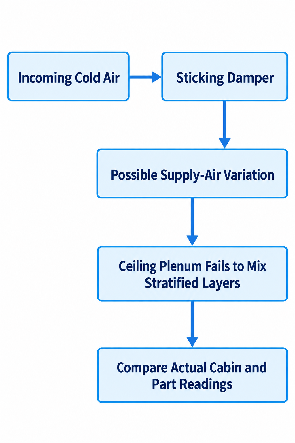
Diagram description
- Incoming Cold Air
- Sticking Damper
- Possible Supply-Air Variation
- Ceiling Plenum Fails to Mix Stratified Layers
- Compare Actual Cabin and Part Readings
- Incoming Cold Air → Sticking Damper
- Sticking Damper → Possible Supply-Air Variation
- Possible Supply-Air Variation → Ceiling Plenum Fails to Mix Stratified Layers
- Ceiling Plenum Fails to Mix Stratified Layers → Compare Actual Cabin and Part Readings
- Incoming Cold Air points RIGHT to Sticking Damper.
- Sticking Damper points DOWN to Possible Supply-Air Variation → Ceiling Plenum Fails to Mix Stratified Layers → Compare Actual Cabin and Part Readings.
Sensor Mechanics and Control Hardware
The control panel can only respond to the data its sensors provide. If a sensor is compromised, the control loop drives the burner based on false assumptions.
- Boundary Layer Air Wash: If an RTD sensor is mounted too close to an intake diffuser, it registers high-velocity discharge air before that air distributes across the cabin, throttling the burner prematurely. If it is tucked behind an access column or door frame, it sits in dead air, calling for excessive heat.
- Contamination and Overspray: Clearcoat and primer overspray build an insulating sleeve over exposed sensor bulbs. An insulated probe responds slowly to temperature swings, causing severe overshoot and undershoot during the cycle.
- Control Logic Disconnects: Modern panels operate on complex PID (Proportional-Integral-Derivative) algorithms. Review your panel's equipment-specific control guidance before concluding a probe has failed. Never attempt field reprogramming of loop gains or factory burner safety settings without an authorized service technician.
Service Handoff and Technical Validation
If log sheets confirm persistent thermal splits after filters and seals have been inspected, bring in a factory-trained service technician to inspect mechanical and electrical sub-assemblies.
SERVICE DISPATCH PROTOCOL
- Provide Completed Thermal Observation Log (Air, Surface, Setpoint, Time)
- Document Recent Differential Pressure Gauge Readings (Magnehelic/Manometer)
- List Recent Physical Changes (Filter Change Dates, Mechanical Repairs)
- Note Panel Alarms (Modulation limits, Purge failures, Airflow interlocks)
Verifying Technical Coating Requirements
Before assuming a spatial split ruined a batch, verify the material requirements. Review the coating supplier's slow-drying guidance against verified metal temperatures rather than panel air displays.
Where the actual coating data sheet specifies part temperature and a hold time, evaluate that requirement as: Target Temperature on the Part Surface × Duration at That Temperature
A specification requiring 140°F for 30 minutes requires the steel substrate to reach 140°F and dwell there for the full duration. If the control panel reaches 140°F in 5 minutes, but the vehicle rocker panels take 20 minutes to absorb that heat, the coating on the lower vehicle has cured for only 10 minutes at temperature. Adding arbitrary bake time without measuring the steel can over-bake upper assemblies while leaving lower assemblies under-cured.
Qualified Service Validation
Field adjustments to gas manifolds, burner profile plates, motorized recirculation dampers, and control calibrations carry fire and explosion hazards. Qualified service personnel determine the appropriate sensing, heating and airflow tests from the installed equipment documentation. The observation log should support that diagnosis without prescribing burner tuning, gas-pressure changes or damper balancing.
Once service adjustments are complete, repeat your baseline thermal observation log under identical load conditions. Compare the post-service observations with the historical log and documented acceptance criteria, noting whether the original spatial or cycle-related symptom has been resolved.
Need Help Sourcing Replacement Parts or Upgrading Your Booth?
If your diagnostics point to failing sensors, damaged intake plenums, worn door seals, or obsolete control hardware, contact our technical team.
Request a Quote with your booth model, serial number and components under review to discuss suitable equipment or replacement-component options.