
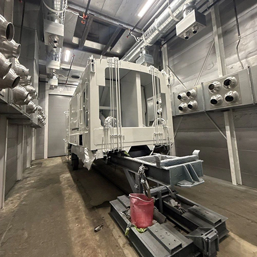
Equipment quotes for industrial spray booths frequently look identical on the surface while masking major differences in base safety functions, engineering documentation, and trade responsibilities. One vendor may include a complete, pre-wired interlock package with hazardous-location fixtures and stamped airflow calculations. Another may supply bare sheet metal panels and an unrated exhaust fan, leaving your electrical and mechanical contractors to engineer life-safety controls in the field.
Comparing proposals requires looking beyond physical dimensions to confirm how each design manages fire, electrical hazards, chemical exposure, and abnormal operating conditions. Using a structured paint booth design checklist during bid review helps isolate what the manufacturer builds, what the installing contractor must provide, and what evidence is required before commissioning.
1. Operating Modes, Chemistry, and Process Containment
A booth's protective architecture must reflect the specific materials applied, the application method, and the thermal profile of the operating cycle. Manual liquid spraying, automated electrostatic bells, powder application, and heated curing cycles each introduce distinct physical risks that dictate enclosure design.
| Operating Phase | Primary Hazard Profile | Protective Response to Verify |
|---|---|---|
| Manual Spraying | Flammable vapor accumulation, operator mist exposure | Required ventilation and applicable applicator interlocks |
| Purge / Evacuation | Residual solvent off-gassing before temperature change | Documented exhaust and transition safeguards for the selected equipment |
| Heated Cure / Bake | Elevated VOC evaporation, thermal runaway risk | Applicable recirculation limits, temperature protection, and access safeguards |
Solvent-borne coatings release volatile organic compounds (VOCs) that form ignitable vapor-air mixtures, while waterborne formulations may still contain combustible ingredients and hazardous overspray; their drying requirements depend on the coating system. If a booth alternates between an ambient spray cycle and an elevated bake cycle, controls must prevent personnel exposure to curing temperatures and purge volatile vapors before burner ignition.
For dual-mode booths, request the manufacturer’s documented airflow paths, applicable recirculation limits, and spray-to-heat transition safeguards. The sequence must suit the approved equipment and process; do not assume a universal damper or purge arrangement.
Confirm which mode controls and safeguards the design requires, which the vendor provides, and which the installing contractors must integrate.
2. Ventilation Dynamics, Airflow Indication, and Service Access
Mechanical ventilation dilutes hazardous concentrations and guides overspray away from the operator's breathing zone toward the exhaust filters. Evaluating ventilation features requires separating particulate filtration from vapor dilution and verifying how exhaust mechanicals are physically isolated from flammable streams.
Particulate Arrestance vs. Solvent Dilution
Paint arrestor exhaust filters capture airborne overspray droplets and solid particulates. They do not capture or remove gaseous solvent vapors. Capturing particulate protects exhaust ductwork, fan impellers, and downstream outdoor surfaces from flammable residue buildup. Diluting solvent vapors below the lower explosive limit (LEL) requires ventilation appropriate to the material release rate and operating conditions; airflow alone does not establish worker exposure control.
Where an applicable air authorization requires vapor abatement, separately designed controls may be needed downstream of particle capture and before discharge; standard booth filter stages will not strip solvent vapors from the exhaust stream.
Airflow Indication and Pressure Gauges
Differential pressure gauges, such as liquid manometers or magnehelic dials, measure the static pressure drop across exhaust filter banks. They alert operators when filters load with paint solids and exhaust resistance rises.
A pressure gauge does not directly measure face velocity or verify that capture velocity reaches every corner of the work envelope. A low differential pressure reading can signify clean filters, but it can also indicate missing filter pads, gaps in the holding frames, or a stalled fan motor.
Ask how the proposal indicates required airflow and provides any applicable alarms or interlocks; a pressure device must be selected and interpreted for the actual system.
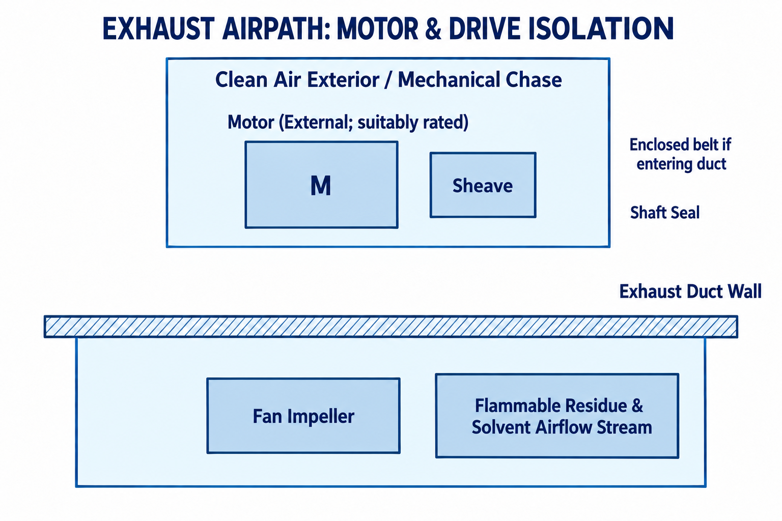
Diagram description
- EXHAUST AIRPATH: MOTOR & DRIVE ISOLATION
- Clean Air Exterior / Mechanical Chase
- Motor (External; suitably rated)
- M
- Sheave
- Enclosed belt if entering duct
- Shaft Seal
- Exhaust Duct Wall
- Fan Impeller
- Flammable Residue & Solvent Airflow Stream
- Clean Air Exterior / Mechanical Chase
- Motor (External; suitably rated)
- M
- Sheave
- Flammable Residue & Solvent Airflow Stream
- Fan Impeller
- Clean Air Exterior / Mechanical Chase: Motor (External; suitably rated), M, Sheave.
- Exhaust Duct Wall: Clean Air Exterior / Mechanical Chase / Flammable Residue & Solvent Airflow Stream.
- Flammable Residue & Solvent Airflow Stream: Fan Impeller.
- Enclosed belt if entering duct; Shaft Seal.
Motor and Fan Drive Placement
Exhaust ductwork accumulates overspray deposits over time, creating a combustible fuel source inside the ventilation envelope. Under OSHA's spray-finishing standard (29 CFR 1910.107(d)(5)), electric motors driving the exhaust fan must never be mounted inside the spray booth enclosure or within the exhaust ducting where hot surfaces and electrical arcs can contact flammable residues.
Under OSHA 1910.107(d)(4), the fan rotating element must be nonferrous or nonsparking, or the casing must be made of or lined with such material, with adequate clearance. Paragraph (d)(6) prohibits belts entering the booth or duct unless the belt and pulley are thoroughly enclosed. Request the actual drive arrangement and maintenance provisions.
When reviewing airflow configurations, verify that the quoted fan and duct dimensions align with OSHA's spray-finishing ventilation requirements (29 CFR 1910.94(c)), whose applicable provisions address ventilation design, duct arrangements, replacement air, and access.
3. Hazardous Electrical Classification, NRTL Scopes, and Interlocks
Where the process creates flammable vapors or mists, the responsible designer must identify the hazardous locations under the applicable electrical requirements, including relevant NEC / NFPA 70 Article 516 provisions. Equipment quotations must clarify which components carry appropriate ratings and how the spray equipment is positively interlocked with the ventilation train.
- Exterior Boundaries: Verify Actual Design
- Exterior classification: determine actual boundaries for process.
- Open doors, access hatches, and exhaust discharge envelopes.
- Interior classification: determine applicable designation.
- Based on materials, operation, and approved design.
- Spray Pattern → Workpiece.
- Suitable equipment and wiring for actual location; verify ratings and any isolation arrangements.
Hazardous Area Boundaries
Ask for drawings showing the actual classifications and boundaries inside and around the spraying area, including openings and connected exhaust. These depend on the materials, process, enclosure, and applicable requirements rather than one universal zone diagram.
Verify suitable fixtures, temperature ratings, wiring methods, and any required sealing or isolation for each actual location. External lighting isolated behind suitable panels is a different arrangement from fixtures mounted within the spray area.
Interpreting NRTL Listings
A listing mark from an approved testing laboratory under OSHA's NRTL program applies only to the specific piece of equipment evaluated, not automatically to the field-erected system as a whole.
A vendor might advertise an "NRTL listed control panel." This listing confirms that the industrial control enclosure was assembled under standards like UL 508A, but it does not certify that the assembled booth enclosure, airflow switches, or external field wiring meet installation codes.
Ask vendors to clarify whether the mark covers the complete integrated package or individual factory components. A component-level listing still leaves your installation team responsible for site-level wiring, grounding, and clearance compliance.
Process Interlocks
Ventilation must operate before spraying can physically begin. Review the process-specific provisions in OSHA paint booth requirements and the approved control design; 1910.107 contains specific interlock requirements for electrostatic and certain heated operations.
Functions to verify where applicable include:
- Compressed air solenoid valves that stay de-energized until the exhaust fan differential pressure switch confirms airflow.
- Power lockouts to electrostatic power packs or fluid delivery pumps tied directly to the ventilation run status.
- Purge-cycle interlocks on dual-mode booths that inhibit heating circuits until a set volume of air changes clears the cabin.
4. Fire Suppression Boundaries and Trade Coordination
A quote that lists "fire damper included" or "fire system ready" does not mean your booth arrives with an operational fire protection system. Clarifying suppression scope early prevents severe project delays and unplanned change orders.
| Booth Manufacturer Scope | Fire Contractor Scope |
|---|---|
| Sheet metal penetration collars / prep cutouts | System flow engineering |
| Any factory duct dampers required by design | Suppression agent and distribution pipework |
| Documented tie-in terminals in booth control panel | Heat detectors / fusible links / manual pull stations |
| Any required damper limit switches | Submittal drawings to local fire marshal (AHJ) |
Confirm the interface and assigned responsibilities for the actual project.
Suppression Types
No universal fire extinguishing agent applies to every booth. Water deluge/sprinkler systems, dry chemical formulations, and gaseous clean agents are each selected based on building infrastructure, applied chemistry, and local authority having jurisdiction (AHJ) directives.
Standard industrial facilities with adequate municipal water supply often tie overhead booth heads directly into the building's wet-pipe sprinkler grid. Operations applying water-reactive chemistries or running specialized robotic cells may require dedicated dry chemical or clean agent suppression cylinders.
The Scope Boundary
Booth manufacturers typically provide pre-punched ceiling collars, mounting brackets, and electrical contact points inside the main control panel. Confirm who designs, supplies, installs, and tests the agent, distribution piping, nozzles, detection, and release equipment; these responsibilities may be assigned to the supplier or qualified fire-protection contractor.
Verify whether the booth vendor includes automatic exhaust fan shutoff and makeup air damper trips within their panel logic. Have the responsible fire-protection designer document the required response of ventilation, spray equipment, and any dampers for the selected suppression system and applicable requirements.
5. System Responses to Abnormal Operating Conditions
A paint booth's safety posture is proven by how the system behaves when components fail. Request the documented safe response to each relevant failure; whether equipment stops or ventilation continues depends on the approved design and condition.
| Trigger Condition | System Response to Verify |
|---|---|
| Exhaust Fan V-Belt Loss | How actual airflow is proved and applicable spray shutdown or alarms operate |
| Door Opened During Cure | Documented heating, ventilation, and access safeguards for that condition |
| High Plenum Static Loss | How abnormal pressure or filter conditions are detected and managed |
| Emergency Stop Actuation | Which application, heat, drive, and ventilation equipment stops or remains active |
Request the vendor’s logic matrix and sequence of operations to evaluate these critical scenarios:
- Fan Drive Failure: If an exhaust fan belt snaps, an amp sensor on the motor may still read an operating motor while zero air moves. Ask how the actual airflow is proved and what required interlocks do on loss of ventilation; motor run status alone may not establish airflow.
- Excess Temperature: Ask for the heating-control and independent limit-protection arrangement required for the selected equipment, including the documented response to excessive temperature and reset conditions.
- Door Switch Tripping: If an operator opens an access door during a high-temperature bake cycle, verify the documented response and safeguards against thermal injury. During spray modes, door switches can either alert operators or interlock with application equipment, depending on process classification.
- Emergency Stop (E-Stop) Integration: Request the emergency-stop circuit and identify which equipment stops, which remains active, and how the response coordinates with ventilation and fire protection for this design.
Demanding complete paint booth certification documentation during the submittal phase exposes whether the manufacturer has engineered these fail-safe interlocks into their standard drawing set or if they expect your plant electrician to construct safety loops from scratch.
6. Physical Ergonomics, Egress, and Operation Training
A booth can satisfy airflow and electrical codes while failing basic physical safety checks if layout and maintenance access are overlooked. Walkways, doors, and service clearances require dedicated review during layout engineering.
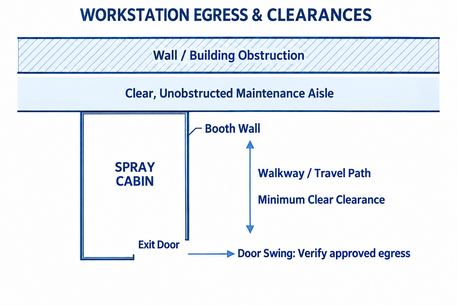
Diagram description
- WORKSTATION EGRESS & CLEARANCES
- Wall / Building Obstruction
- Clear, Unobstructed Maintenance Aisle
- Booth Wall
- SPRAY CABIN
- Walkway / Travel Path
- Minimum Clear Clearance
- Exit Door
- Door Swing: Verify approved egress
- Booth Wall
- SPRAY CABIN
- Exit Door
- Walkway / Travel Path
- Minimum Clear Clearance
- Wall / Building Obstruction / Clear, Unobstructed Maintenance Aisle / Booth Wall.
- SPRAY CABIN: Exit Door → Door Swing: Verify approved egress.
- Walkway / Travel Path: Minimum Clear Clearance.
- Walkways and Unobstructed Egress: Spray booths must provide direct egress paths for personnel working inside. Verify the required door arrangement and exit travel under applicable ventilation and egress provisions, keeping access unobstructed by equipment, columns, or mixing tables.
- Filter Changeout Ergonomics: Operators frequently neglect or postpone filter maintenance when filter racks are hazardous or difficult to reach. Crossdraft exhaust walls and downdraft pit holding frames must allow quick service without forcing workers to balance on narrow ledges or enter unventilated exhaust plenums without lockouts.
- Service Access: Fan bearings, motor drives, and damper linkages require routine service. If the exhaust fan is mounted 20 feet up in a roof plenum, confirm whether the vendor provides service access platforms, ladders, and tie-off points, or if routine lubrication will require renting secondary lifts.
- Documentation and Hands-on Training: Equipment longevity depends on operator knowledge. Industrial manufacturers like Rohner supply extensive factory engineering drawings, schematics, and operations manuals to establish baseline maintenance intervals. High-value quotations include factory-backed commissioning support and on-site training for plant maintenance teams covering filter replacement protocols, airflow calibration, and interlock testing.
7. Safety Feature, Function, and Evidence Verification
Use this matrix to cross-check competing booth proposals. Look for explicit submittal deliverables rather than verbal assurances.
| Protective Component | Primary Safety Function | Bid Evidence & Submittals to Request | Common Scope Gap / Risk |
|---|---|---|---|
| Exhaust Fan & Drive Package | Dilutes VOCs; exhausts overspray mist without mechanical ignition risks. | Fan curves; non-sparking wheel certification; external motor mounting detail. | Motor mounted inside duct air stream; general-purpose fan impeller provided. |
| Airflow Monitoring Device | Tracks static resistance across filter media; alerts on flow drop. | Manometer/gage specification sheet; pressure switch wiring diagram. | Airflow indication or applicable interlock responsibilities unclear; gauge mistaken for direct velocity measurement. |
| Hazardous Area Fixtures | Illuminates spray area without igniting flammable atmospheric vapors. | Fixture cut sheets with Class/Division/Zone NRTL marks and temperature ratings. | Unrated commercial LED light fixtures supplied for internal spray zone. |
| Spray Applicator Interlock | Prevents spraying if exhaust ventilation is offline or degraded. | Electrical schematic showing air solenoid valve or pump circuit interlock. | Valve or relay omitted; vendor labels interlock as "by electrical contractor." |
| Mode Purge Controls | Evacuates volatile vapors prior to energizing curing heat sources. | Sequence of operations documentation; control panel logic flow sheet. | Timer logic left unprogrammed; manual switches used instead of automated cycles. |
| Emergency Stop System | Provides the documented emergency response for application equipment and heat sources. | Electrical control drawing showing the emergency-stop circuit and equipment response. | Emergency response undocumented or incompatible with the approved control design. |
| Fire Protection / Ventilation Coordination | Coordinates ventilation and spray equipment with the selected fire-protection system. | Approved response sequence and interface drawings; damper details only where the design includes them. | Required interfaces or contractor responsibilities omitted; unsupported assumptions about fan or damper response. |
| Access & Egress Hardware | Allows rapid exit during fires or emergencies; seals cabin during run. | Door hardware schedule; swing direction layout on engineering submittals. | Door arrangement or escape hardware that fails applicable egress requirements. |
8. Clarifying Safety Scope Before Issuing a Purchase Order
Vague line items on a quotation create costly project delays and compliance gaps during municipal inspections. Before you sign an equipment contract or release progress payments, demand written clarification on who owns each critical safety boundary.
When you request a paint booth quote, bring these specific data points to the conversation:
- Target Coating Chemistries: Provide exact safety data sheets (SDS) showing solvent carriers, flash points, and volatile content so the vendor sizes airflow dilution correctly.
- Application Methods: Specify whether you apply coatings manually with pneumatic guns, use airless equipment, or run high-voltage electrostatic bells, which require specialized interlock loops.
- Facility Utility Matrix: Identify available electrical service (voltage/phase), natural gas or propane pressures, and building fire sprinkler capacity.
- Contractor Trade Boundaries: Require the vendor to itemize the division of labor between factory supply, mechanical duct installation, electrical control wiring, and field fire suppression commissioning.
Forcing vendors to address these points in writing separates complete, code-aligned engineering packages from bare equipment shells, protecting both your operators and your capital budget.