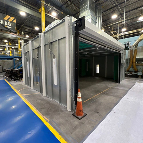
Scaling up an automotive enclosure alone does not establish a suitable truck paint booth. Commercial fleet vehicles present radically different physical profiles, access challenges, and building demands than passenger cars. A layout that accounts only for bumper-to-bumper vehicle length frequently fails once extended side mirrors, rooftop refrigeration units, open service doors, and elevated spray platforms enter the equation.
Proper planning requires establishing clear vehicle admission boundaries, mapping shop floor travel paths, selecting an airflow style that matches your building's structural limits, and integrating upper-surface access equipment before finalizing building drawings.
The Vehicle Admission Matrix
Truck paint booths cannot be sized around average vehicle specs because universal commercial vehicle dimensions do not exist. Sizing must be dictated by your defined admission profile: the regular production fleet that justifies the investment, separated carefully from occasional oversize jobs that may require special handling or off-site processing.
Every measurement must account for the vehicle in its active paint-prep or spray configuration. Extended side mirrors, open cab doors, rear roll-up doors, dropped tailgates, and rooftop climate packs all expand the clearance required inside the cabin. Before establishing custom parameters, use a paint booth measurement guide to structure the actual vehicle and handling measurements, then apply your fleet-specific additions.
| Vehicle Family | Critical Outer Appendages | Operational Orientation & Enclosure State | Layout & Admission Checks |
|---|---|---|---|
| Class 8 Day Cabs & Sleepers | West Coast mirrors, dual exhaust stacks, chassis fairings, rear cab extenders | Cab doors cracked or masked; hood tilted for jamb access during prep | Mirror-tip to mirror-tip width; total height from road to exhaust stack tip; turning swing into the front door |
| Straight Trucks & Dry Freight Vans | Curbside side-access doors, fold-away rear liftgates, rooftop refrigeration units | Liftgates lowered, folded, or deployed; rear barn doors pinned back flat against body | Overall length with liftgates deployed; overall height including refrigeration units; door header clearance |
| Service & Utility Bodies | Outrigger pads, side toolboxes, top-mounted ladder racks, knuckle-boom cranes | Compartment doors hinged open 90° to 180°; crane booms cradled in transport position | Lateral aisle width with cabinet doors open; total height of cradled booms or racks |
| Transit & Tour Buses | Exterior destination signs, curb-view mirrors, rear bike racks, rooftop battery or CNG pods | Enclosed profile, minimal door swing; long wheelbase requiring wide turning radius | Front and rear overhang swing during turns; overall roof pod height; drive-through exit space |
| Refuse & Vocational Equipment | Front-load lift arms, top hoppers, roll-off hoists, chassis tanks | Hoppers lowered; packer blades secured; side mirrors and steps fully projected | Total width across widest steps or hinges; vertical clearance over top-mounted hydraulic lines |
Separating Production Work from Extreme Exceptions
Designing a booth to fit a 60-foot articulated bus when 90% of your weekly volume consists of 26-foot straight trucks creates chronic operational inefficiency. An oversized cabin requires massive air handling systems, higher burner input, and increased filter replacement costs across every cycle.
If odd-sized vocational units only visit the shop once a quarter, size the cabin around your core commercial workload. Let high-frequency vehicles set the standard working envelope, and evaluate whether rare exceptions can be painted in assemblies or managed through dedicated prep areas.
Vehicle Path and Door Configuration
The space outside a truck booth governs internal layout choices. A booth positioned with inadequate exterior approach clearance will lead to damaged door frames, stalled staging areas, and lost production hours.
| Loading Strategy | Layout to Verify |
|---|---|
| Drive-through | Staging, entry, cabin, exit and outfeed clearances for the actual vehicle |
| Drive-in and back-out | Entry apron, door clearance, reverse travel and separation from incoming work |
Approach and Turning Radiuses
Verify the actual turning and alignment path of long-wheelbase vehicles and tractor-trailers; a universal approach-length multiplier cannot establish clearance. If an entrance must face an interior shop aisle, that aisle must provide enough apron depth to accommodate the vehicle's turning track without striking opposite walls or staging lines.
Clear Door Openings vs. Installed Door Travel
Clear opening dimensions are not identical to nominal booth frame dimensions:
- Roll-up rubber or fabric doors consume overhead headroom for barrel assemblies and bottom bars, lowering the usable entry height.
- Bi-fold and multi-panel swing doors consume floor radius when opening and can reduce net entrance width if the panels do not open flat against the exterior or interior walls.
- Hardware clearances must accommodate tow hooks, side mirrors, and elevated marker lights with a consistent perimeter margin.
Drive-Through vs. Drive-In / Back-Out
- Drive-through configurations create linear production flow from prep to paint to flash/cure. They can separate incoming and outgoing work when staging and air movement are controlled. However, they require double the door infrastructure, dual clear zones inside the building, and sufficient runway at the exit end to pull vehicles fully clear of the rear doors.
- Drive-in / back-out configurations can reduce exit-side staging space, while still requiring the specified equipment and service clearances. The tradeoff is logistical: painted units must be backed out through the incoming staging line, which requires dedicated apron space and increases cycle handoff times.
Airflow Infrastructure and Building Interfaces
Selecting an airflow design for a large cabin involves weighing structural building modifications against daily finish quality. Different truck and large-equipment booth configurations place vastly different mechanical demands on your facility.
Manufacturers document bolted panel construction and distinct manufacturer airflow configurations designed to match specific structural envelopes. Rather than asking which airflow style is universally superior, evaluate which design aligns with your concrete slab, ceiling structure, and available floor space.
| Airflow Configuration | Path and Building Interface |
|---|---|
| Crossdraft | Front-to-rear airflow; confirm rear plenum and duct space |
| Side downdraft | Ceiling supply to low side exhaust; confirm overall width |
| Pit downdraft | Ceiling supply to below-floor exhaust; confirm civil work and vehicle support |
Crossdraft Configurations
Crossdraft booths draw air through the front entry doors (or a front intake plenum) and pull it horizontally across the length of the vehicle into a rear exhaust bank.
- Building Interface: Minimal civil work. They sit directly on an existing level concrete slab without floor pits or elevated basements.
- Footprint Impact: Consumes linear length to accommodate the rear exhaust plenum and fan tower.
- Airflow Considerations: Air travels over the front of the vehicle before reaching the back. Overspray from upfront operations can drift past downstream surfaces, requiring a spray sequence suited to the coating, airflow and work.
Side-Downdraft Configurations
Side-downdraft booths introduce replacement air through a full-length ceiling plenum and draw it downward and outward into exhaust plenums built along the bottom of the side walls.
- Building Interface: Eliminates the need for concrete cutting or pit excavation while delivering a downward-diagonal airflow pattern that clears overspray away from upper panels quickly.
- Footprint Impact: Significantly widens the overall equipment envelope. The side exhaust plenums add structural width along both walls, which can encroach on adjacent shop travel lanes.
Pit-Downdraft Configurations
Pit-downdraft systems bring air straight down from the ceiling through the cabin floor grating into concrete exhaust trenches.
- Building Interface: Requires extensive civil engineering. Concrete cutting, soil condition analysis, and deep pit forming are mandatory. High water tables, radiant floor heating loops, or shallow bedrock can drastically increase installation complexity.
- Footprint Impact: Maximizes usable shop floor space around the booth perimeter because exhaust filtration sits below grade rather than in lateral wall plenums.
- Airflow Considerations: Directs airflow downward; verify distribution around the actual vehicle and access equipment.
Mechanical Integration
Any selected configuration requires coordinated paint booth exhaust planning to route high-volume ducting through roof trusses, position make-up air units (MAUs), and secure fuel lines without conflicting with existing building cranes or structural columns.
Elevated Access and Sightline Engineering
Vehicle height alone does not dictate the vertical clearance of a truck booth. A vehicle-to-ceiling height difference alone cannot establish sufficient upper-surface access. Technicians require proper line of sight, correct spray gun orientation, and room for elevated working platforms to apply coatings to horizontal surfaces.
Vertical access check: Include vehicle roof equipment, the platform’s operating envelope, the operator’s reach and spray stroke, and clearance from ceiling lights and other obstructions.
The Geometry of Upper-Surface Finishing
Applying primers and clearcoats requires holding the spray gun perpendicular to the substrate at the distance specified for the gun and coating. When finishing high-roof vans, sleeper caps, or tanker tops, spraying from floor level results in dry spray, uneven film build, and missed edges.
The vertical working envelope must include:
- Maximum vehicle height with roof equipment installed.
- Operator standing height on elevated access equipment.
- Gun stroke clearance between the operator's head and the ceiling light fixtures.
Integrating Access Equipment
Moving ladders and rolling scaffolding inside a production truck booth creates safety risks and disrupts airflow. Evaluate whether wheeled scaffolds crowd side aisles, disturb cleanliness or block lighting.
For ongoing fleet refinishing, evaluate paint booth lifts alongside other suitable access methods, checking the model’s travel and operating envelope. Integrating mechanical lifts impacts the total booth layout:
- Cabin Width: The booth interior must be wide enough to house the vehicle, the retracted and extended lift travel envelope, and safe operating space along the vehicle side.
- Lighting Sightlines: Light fixtures must be angled and positioned so that the lift platform does not cast a continuous shadow over the working surface as the technician moves along the wall.
- Supply Lines: Air drops, breathing air lines, and electrostatic grounds must route directly onto the access equipment without dragging across wet finishes or floor gratings.
Layout Verification Before Equipment Ordering
Before signing off on equipment drawings, verify the difference between working and overall booth dimensions. The interior working space defines what fits inside; the exterior overall dimension determines whether the booth fits into your facility alongside required service zones.
| Layout Layer | What to Include |
|---|---|
| Working interior | Vehicle, deployed gear, operator and access equipment |
| Overall equipment | Cabin, plenums, columns and mechanical projections |
| Facility space | Equipment footprint, loading path, required service access and overhead route |
Use this verification matrix to evaluate candidate layout drawings against physical operations:
| Parameter | What to Verify on the Layout Drawing | Rejection Trigger |
|---|---|---|
| Clear Door Width | Measure between innermost jambs, rub rails, or seal retainers. | Less than total vehicle mirror-to-mirror width plus required perimeter maneuvering margin. |
| Door Inswing / Outswing | Plot the swing arc or bi-fold fold-out depth against walls and staging lines. | Door panel hits an aisle column, prep stall, or pedestrian egress path when fully opened. |
| Ceiling Structural Height | Compare overall booth height (including exhaust stack transitions and intake hoods) against building joists. | Interference with crane bays, overhead gas lines, lighting trusses, or fire sprinkler drop patterns. |
| Lateral Wall Aisle Width | Space between vehicle rub rails and wall plenums or retracted man-lift platforms. | Insufficient room for technicians to maneuver spray guns and inspection lights alongside vehicles. |
| Pit Grating Layout | Grated exhaust footprint versus actual axle widths and tire contact points. | Wheel tracks directly bear on non-load-bearing pit grates or fall outside the designed wheel-support tracks. |
| Air Make-Up Siting | Path and length of ductwork from the heater to the booth intake plenum. | Intake duct requires structural wall penetrations that violate local zoning or building fire ratings. |
| Filter Service Access | Clear access corridors to exhaust filter banks, pit cleanout trays, and roof-mounted fan motors. | Filter access doors trapped against facility walls, requiring equipment disassembly to swap filters. |
Establishing Drawing Responsibilities
Never assume that an equipment layout drawing accounts for your facility's local codes or building boundaries. Equipment manufacturers provide drawings that define the booth's internal geometry and structural connection points.
Your facility engineering team, local mechanical contractors, and civil engineers remain responsible for:
- Verifying that the concrete slab thickness and rebar structure support point-loading from booth columns and vehicle axle weights.
- Confirming adequate utility supplies (natural gas pressure, electrical service ampacity, compressed air CFM).
- Ensuring building structural compliance for roof penetrations, wind-load ratings for exterior exhaust stacks, and seismic tie-downs.
Gather your exact vehicle measurements, access requirements, and facility dimensions, then request a truck-booth layout quote to generate an engineered design built specifically for your fleet operations.