
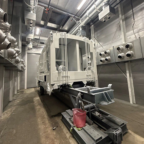
Modular construction simplifies paint booth delivery and field assembly, but it does not turn an industrial spray booth into a simple plug-and-play appliance. While factory-formed wall panels bolt together predictably inside an existing shop, the booth enclosure is only one part of a tightly regulated thermodynamic and mechanical system.
Finishing managers evaluating equipment proposals must distinguish between the enclosure panels and the engineered equipment that drives them. Standardized panels offer clear advantages for shipping, tight factory footprints, and predictable assembly. However, building constraints, exhaust paths, code compliance, and utility drops will dictate project success far more than the panel joint design.
What Modular Construction Changes (and What Remains an Engineered System)
Modular spray booths rely on standardized, prepunched sheet metal panels—with materials and panel gauges varying by model—assembled on-site using mechanical fasteners rather than field welding. When comparing industrial paint booth options, this structural approach is used in commercial finishing operations ranging from automotive refinish shops to large equipment fabricators.
The real advantage of bolted panel construction is repeatable factory quality control and practical site delivery. Panelized shipments can simplify access, but crate dimensions, structural members, and lifting needs must still be checked against the delivery route. For facilities with constrained entryways or interior installations situated far from an exterior loading dock, panelized construction makes delivery feasible where a pre-welded cabin would be impossible to stage.
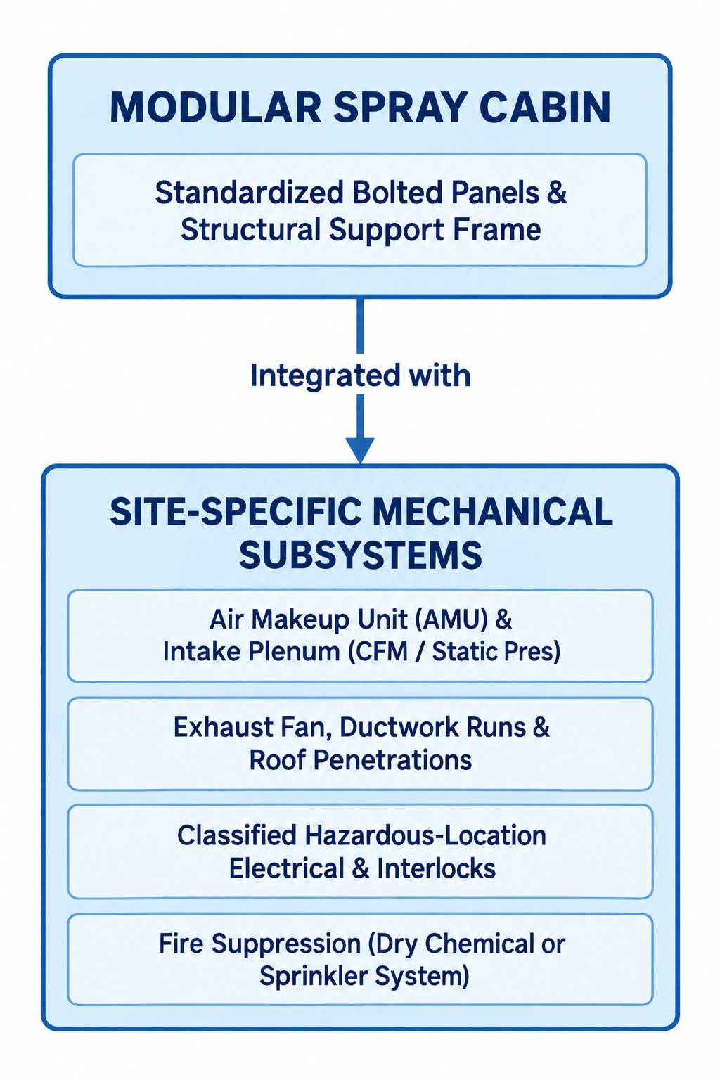
Diagram description
- MODULAR SPRAY CABIN
- Standardized Bolted Panels & Structural Support Frame
- Integrated with
- SITE-SPECIFIC MECHANICAL SUBSYSTEMS
- Air Makeup Unit (AMU) & Intake Plenum (CFM / Static Pres)
- Exhaust Fan, Ductwork Runs & Roof Penetrations
- Classified Hazardous-Location Electrical & Interlocks
- Fire Suppression (Dry Chemical or Sprinkler System)
- MODULAR SPRAY CABIN → SITE-SPECIFIC MECHANICAL SUBSYSTEMS: Integrated with
- MODULAR SPRAY CABIN
- Standardized Bolted Panels & Structural Support Frame
- SITE-SPECIFIC MECHANICAL SUBSYSTEMS
- Air Makeup Unit (AMU) & Intake Plenum (CFM / Static Pres)
- Exhaust Fan, Ductwork Runs & Roof Penetrations
- Classified Hazardous-Location Electrical & Interlocks
- Fire Suppression (Dry Chemical or Sprinkler System)
- MODULAR SPRAY CABIN contains Standardized Bolted Panels & Structural Support Frame
- Cabin downward arrow labelled Integrated with to SITE-SPECIFIC MECHANICAL SUBSYSTEMS
- Subsystem container holds four bullet labels; no connecting arrows among bullets
The booth cabin, however, does not function in isolation. The wall and ceiling panels merely define the spray envelope. The complete installation requires an engineered assembly of discrete subsystems:
- Air-handling and filtration: Intake plenums, exhaust chambers, and filter racks designed to direct airflow across the part.
- Mechanical exhaust: Fans, belts, and motors sized to overcome total system static pressure (cabin, filters, ductwork, and weather cap).
- Safety interlocks and controls: Controls and interlocks appropriate to the equipment and coating process.
- Thermal units: Where specified, direct-fired or indirect-fired air makeup units (AMUs) supply replacement air and process heating.
Treating a modular booth as an off-the-shelf kit overlooks these interdependencies. If an enclosure is assembled without matching the exhaust fan output to the specific duct layout, or if the intake filtration area restricts airflow, the modular design provides no operational benefit.
Matching the Enclosure to the Workpiece and Facility Constraints
A booth must fit both the largest parts you produce and the structural reality of your plant floor. Evaluating physical fit requires checking both the clear interior envelope and the total installed footprint, which includes structural frames, fan housings, and maintenance clearances.
Before committing to a specific layout, finishing teams should cross-reference their shop layout against standard paint booth design requirements. Exterior dimensions on an equipment cut sheet rarely reflect the total clearance required to operate and maintain the system safely.
| Design Parameter | Operational Metric | Facility Impact |
|---|---|---|
| Clear Working Height | Tallest part + rigging and model-specific working clearance | Ceiling joist and crane hook height |
| Working Width | Widest part + required operator and airflow space | Distance to adjacent equipment and walkways |
| Working Length | Longest part + door access and working space | Main aisle traffic and staging zones |
| Exhaust Fan Footprint | Fan housing + transition duct + motor offset | Side, rear, or overhead clearance for belt servicing |
| Door Swing Arc | Radial path of swing doors or overhead rollup tracks | Forklift travel paths and electrical disconnect access |
Air velocity standards also dictate internal geometry. Under OSHA 1910.107, finishing enclosures must satisfy strict mechanical ventilation requirements to dilute flammable vapors and keep overspray moving toward exhaust filters. For conventional dry-filter booths covered by OSHA 1910.107(b)(5)(i), non-electrostatic spraying requires an average velocity of at least 100 feet per minute across the open face or booth cross-section. At a fixed design velocity, a larger cross-section requires more airflow (CFM), which can increase fan and conditioned-air demand.
Material handling determines door and structural designs. Roll-up doors require overhead wall height that can conflict with existing crane runways. Swing doors require dedicated floor area that cannot be blocked by raw material staging. For parts moved via overhead monorails, roof openings need manufacturer review to preserve structural support and the intended airflow pattern.
Facility floors introduce another mechanical hurdle. Bolted panel systems rely on level concrete to achieve tight panel seams and square door frames. Reviewing the manufacturer installation documentation prior to delivery will establish acceptable slab slope tolerances. For the GFS General Industrial Booth covered by that manual, a floor more than a quarter-inch out of level requires shimming or grouting; other equipment must follow its own installation requirements.
Verifying Long-Term Flexibility Before Paying a Premium
Equipment buyers frequently pay extra for modular systems under the assumption that they can easily alter or move the enclosure later. In practice, future structural changes are never as simple as bolting on an extra wall section or unbolting the frame for a fast weekend move.
When evaluating the feasibility of expanding an existing paint booth, the enclosure panels are the easiest variable to solve. The limiting factor is fluid dynamics. Airflow through a spray booth follows basic mass-flow principles:
Airflow Volume (CFM) = Cross-Sectional Area (sq ft) × Design Face Velocity (FPM)
As an illustration, extending the length of a 14' × 12' crossdraft booth leaves its cross-sectional area unchanged, while airflow distribution and system resistance still need review. At the same assumed 100 FPM design velocity, increasing width or height raises the calculated airflow volume proportionately:
- Baseline: 14' W × 12' H = 168 sq ft Area × 100 FPM = 16,800 CFM Required
- Expanded: 18' W × 14' H = 252 sq ft Area × 100 FPM = 25,200 CFM Required
- 50% CFM Increase: Review
- Larger Fan & Motor
- Increased Duct Diameter
- Higher-Output AMU Burner
An air-handling package that can deliver only 16,800 CFM cannot meet a 25,200 CFM design demand. Adding modular structural bays requires checking the fan performance, replacement air, and filtration against the revised design; panel flexibility alone does not establish adequate ventilation.
Relocating an installed booth carries similar challenges. While bolted panels can be disassembled, the installer must assess which seals, gaskets, and fasteners can be reused under the manufacturer’s requirements. Confirm applicable building, electrical, and fire requirements with the Authority Having Jurisdiction (AHJ) before committing to a move; changed site conditions or required upgrades can affect the budget.
Comparing Complete Proposals Beyond the Shell
The booth shell is only one part of the total installed capital cost. Comparing equipment proposals solely on panel gauge or crate price obscures the substantial scope of work required to commission the system.
When evaluating vendor proposals, separate the factory package from the balance-of-plant responsibilities.
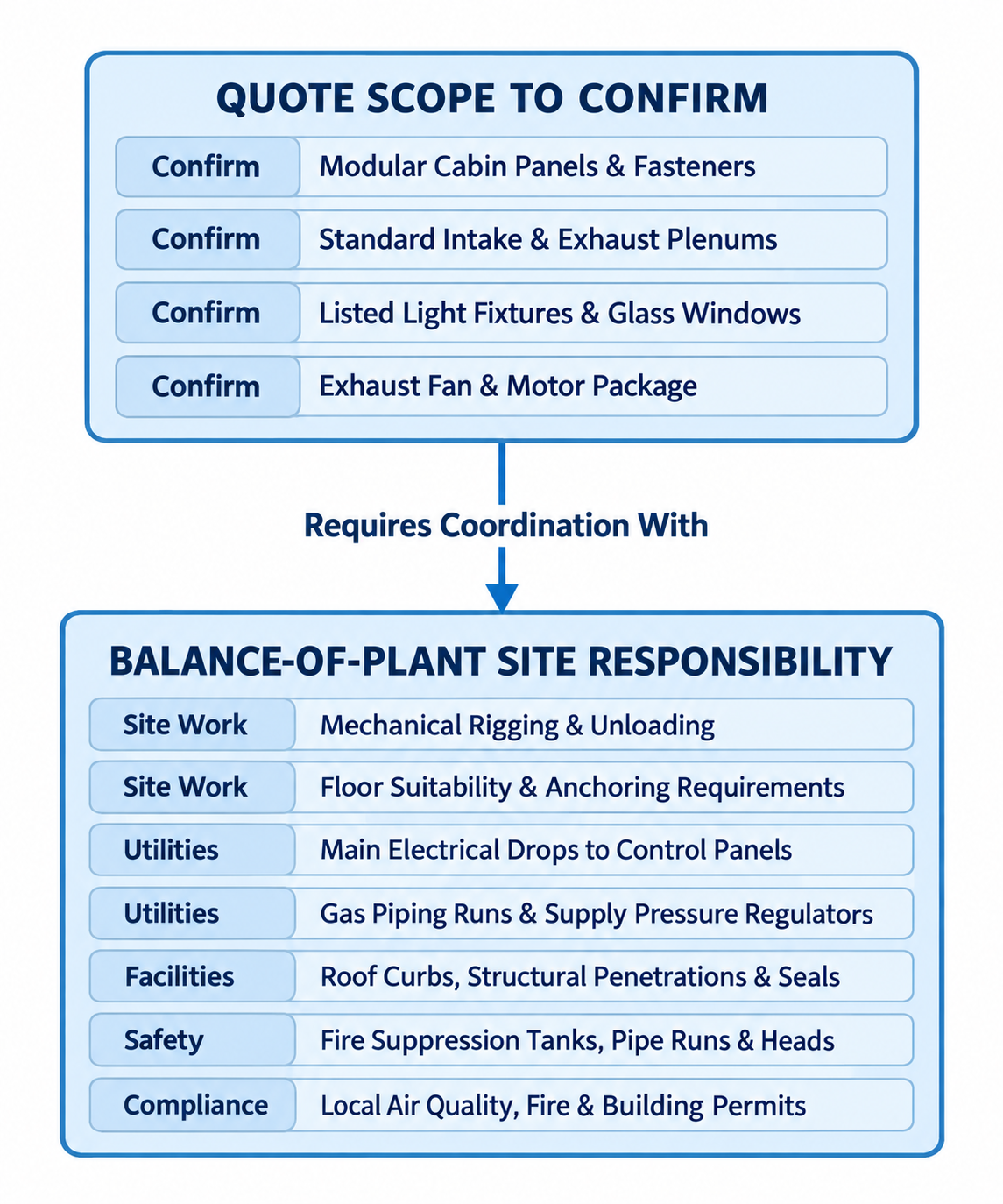
Diagram description
- QUOTE SCOPE TO CONFIRM
- Confirm
- Modular Cabin Panels & Fasteners
- Standard Intake & Exhaust Plenums
- Listed Light Fixtures & Glass Windows
- Exhaust Fan & Motor Package
- Requires Coordination With
- BALANCE-OF-PLANT SITE RESPONSIBILITY
- Site Work
- Mechanical Rigging & Unloading
- Floor Suitability & Anchoring Requirements
- Utilities
- Main Electrical Drops to Control Panels
- Gas Piping Runs & Supply Pressure Regulators
- Facilities
- Roof Curbs, Structural Penetrations & Seals
- Safety
- Fire Suppression Tanks, Pipe Runs & Heads
- Compliance
- Local Air Quality, Fire & Building Permits
- QUOTE SCOPE TO CONFIRM → BALANCE-OF-PLANT SITE RESPONSIBILITY: Requires Coordination With
- QUOTE SCOPE TO CONFIRM container has four Confirm rows.
- Tags are row categories, not flow nodes.
A disciplined proposal evaluation requires clarifying which trade handles each boundary connection:
- Mechanical erection: Does the quote provide union or non-union mechanical assembly, or does it assume your shop maintenance team handles uncrating, standing structural steel, and panel bolting?
- Ductwork and penetrations: Confirm whether duct transitions, duct runs, roof curbs, supports, weather caps, and roof sealing are included or require separate contractors.
- Electrical integration: Confirm the supplied lighting and controls, and assign qualified electrical trades to review the applicable hazardous-location requirements and complete the site connections.
- Fire protection system: Confirm whether fire protection is included, who designs and installs it, and what review and acceptance the local authority requires for the proposed system.
To build an accurate budget, establish a written project brief documenting your incoming utility capacities, roof height, available slab area, and specific process requirements. Once you have documented your shop parameters, request a project quote that itemizes both equipment delivery and commissioning support so you can compare modular options against real-world installation costs.