
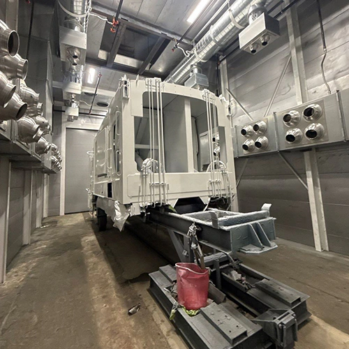
A low initial quote for a paint booth frequently turns into an expensive field modification. Finishing business owners often discover that an attractively priced equipment package excluded the exhaust duct transitions, omitted the intake filter ceiling, or assumed a three-phase electrical supply that the shop floor does not possess.
To buy a spray booth that meets your operational needs without unexpected site expenses, you must work backward from your process. A complete specification defines the chemistry you apply, the parts you handle, and the physical constraints of your building. This guide outlines how to build an equipment specification, evaluate airflow and site readiness, and compare manufacturer proposals on equal footing.
Define the Workpiece, Chemistry, and Production Throughput
Equipment selection starts with the physical parts moving through your finishing department. A booth configured for high-mix batch work has completely different handling and ventilation demands than one built for long structural steel or high-speed automotive refinishing.
- PART PARAMETERS
- Dimensions (L x W x H)
- Staging / Flash-off Space Requirements
- Weight & Handling Method
- Target Finish Standard (Class A vs. Shop)
- PROCESS CHEMISTRY
- Solvent-borne vs. Waterborne
- Catalyst & Flash-off Timing
- Solid Overspray Capture
- Ambient Air Cure vs. Forced-Heat Bake
- PRODUCTION CAPACITY
- Target Parts per Shift
- Batch vs. Conveyor Flow
- Color-Change Frequency
- Buffer Space for In-Booth Masking
Workpiece Envelope and Part Handling
Measure the single largest part you intend to finish, including any mounting hardware, lifting eyes, or dollies. Then consider how that part enters and exits the space.
- Rolling stock and carts: Require unobstructed entry thresholds, adequate turning radius outside the doors, and floor tracks or flat plate floors where caster wheels will not bind.
- Overhead monorails or cranes: Require roof-slot openings, external structural gantry clearance, and continuous weather seals around conveyor tracks.
- Manual carrying: Requires designated operator walking clearance on both sides of the part—the selected manufacturer’s clearances for workpiece access, spraying, and safe movement.
Sizing only for the part itself creates a severe operational bottleneck. Operators need room to maintain proper gun distance and angle without backing into intake filters or bumping into walls.
Coating Chemistry and Curing Demands
Your material choice dictates your airflow volume, flash-off protocols, and temperature control needs. Formulate your spray-finishing requirements by reviewing your coating manufacturer's technical data sheets (TDS).
Solvent-borne coatings, waterborne formulations, polyurethanes, and two-component epoxies perform differently under varying air velocity and humidity conditions:
- Waterborne finishes rely on high air turnover and low relative humidity to evaporate water carriers efficiently. Accelerated flash-off often requires supplemental blowers or specialized ceiling diffusers.
- Solvent-based paints require calculated exhaust volumes to keep flammable vapor concentrations well below the lower explosive limit (LEL) during peak delivery rates.
- Cure profiles: If your shop requires rapid turnaround, an ambient-air cure cycle limits production capacity. Evaluate any heated cycle against the coating data sheet and selected equipment; heating adds equipment-specific utility and control requirements to the project scope.
Filtration reality: Standard exhaust arrestor pads capture particulate overspray (resin, pigments, and solids). They do not extract volatile organic compounds (VOCs). Gaseous solvent vapors pass directly through standard fiberglass or paper arrestors and are evacuated into the outdoor atmosphere. If your facility has strict mass emission limits or requires VOC reduction, have the environmental requirements and suitable control options evaluated separately from ordinary overspray filtration.
Align the Physical Envelope and Airflow Configuration to the Finish Quality
A paint booth is fundamentally an air-handling device built to manage overspray, protect operators, and prevent contamination on wet parts. Selecting between configurations requires balancing finish expectations against installation budgets.
To choose the right paint booth size, you must distinguish between interior clear working dimensions and the overall exterior footprint. Standard manufacturer catalogues show that the exterior height and width routinely exceed interior dimensions by model-specific amounts once you account for upper plenum framing, exterior lighting housings, door hardware, and fan mountings.
| Airflow Style | Process Review | Facility Requirements |
|---|---|---|
| Open-Face | Plant-air cleanliness | High shop air draw; open area |
| Crossdraft | Part and spray sequence | Simple concrete; flat floor |
| Semi-Downdraft | Intake and part layout | Overhead duct clear; flat floor |
| Side-Downdraft | Ceiling and side exhaust | Wide bay width; no pit excavation |
| Pit Downdraft | Ceiling and floor exhaust | Concrete pit excavation or ramps |
Airflow Architectures Compared
Finishing operations typically evaluate open-face, crossdraft and downdraft paint booths when matching equipment to process demands.
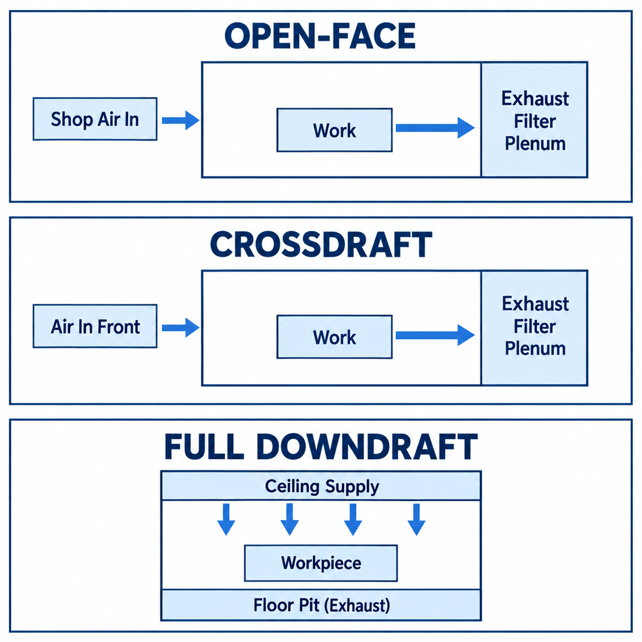
Diagram description
- OPEN-FACE
- Shop Air In
- Work
- Exhaust Filter Plenum
- CROSSDRAFT
- Air In Front
- Work
- Exhaust Filter Plenum
- FULL DOWNDRAFT
- Ceiling Supply
- Workpiece
- Floor Pit
- (Exhaust)
- Shop Air In → Work
- Work → Exhaust Filter Plenum
- Air In Front → Work
- Work → Exhaust Filter Plenum
- Ceiling Supply → Workpiece
- Workpiece → Floor Pit
- Open-face: shop air enters chamber left to right past Work to Exhaust Filter Plenum on right
- Crossdraft: Air In Front enters chamber left to right past Work to Exhaust Filter Plenum on right
- Full downdraft: Ceiling Supply at top; four downward arrows toward Workpiece; Floor Pit beneath chamber with (Exhaust) qualifier
- No links among three panels
Open-Face Booths
Open-face booths enclose three sides while drawing ambient shop air through the front opening and pulling it straight back through an exhaust bank.
- Best for: Small parts, conveyorized production lines, structural shapes, and batch operations where a fully enclosed cabin slows down material transfer.
- Process limitations: Because shop air enters without secondary filtration, airborne dust from nearby grinding or woodworking can enter the spray zone.
- Operational design: Modern open-face models often incorporate multi-stage fan controls. These systems throttle fan speed during non-spraying staging phases, conserving plant electricity and preventing unnecessary loss of heated or cooled conditioned shop air when the spray gun is idle.
Enclosed Crossdraft Booths
Enclosed crossdraft booths pull air horizontally through filtered front product doors, across the workpiece, and out through an exhaust plenum located at the rear of the cabin.
- Documented baseline: Standard commercial enclosures—such as a non-pressurized crossdraft configuration—utilize structural panel assemblies, filtered front entry doors, and a dedicated rear exhaust box.
- Process limitations: Air travels the full length of the cabin. Overspray generated at the front of a large part travels across the rear surfaces before hitting the exhaust filters, requiring thoughtful spray sequence planning from the operator.
- Site advantage: Common rear-exhaust crossdraft configurations avoid an underfloor exhaust pit; verify other slab and site work separately.
Semi-Downdraft Booths
Semi-downdraft units draw air into a ceiling plenum located in the first quarter to third of the booth cabin. The air moves down and backward toward the rear exhaust wall.
- Process advantage: Introduces incoming air above the part, moving overspray down away from the operator’s breathing zone before drawing it back. Evaluate the airflow around your actual parts and the selected exhaust interface rather than assuming a finish-quality ranking.
Downdraft Booths
True downdraft booths draw filtered air uniformly across the entire ceiling plenum and pull it straight down into filtered floor pits or raised basement exhaust channels.
- Process advantage: Gravity and airflow work together. Air draws overspray toward floor exhaust. Actual capture and finish results depend on filtration, loading, air balance, and the coating process.
- Facility impact: Requires excavating single or multi-row concrete floor trenches or engineering a raised steel basement floor with vehicle access ramps.
Cabin Pressurization: Pressurized vs. Non-Pressurized
- Non-pressurized (exhaust-only): The exhaust fan pulls air through intake filters under negative pressure. Any gap in door gaskets, panel seams, or pass-through ports pulls plant dust into the cabin.
- Pressurized cabins: A dedicated supply system coordinates filtered replacement air with exhaust. The required pressure balance and door operating conditions depend on the equipment design and applicable requirements.
Audit Site Readiness, Building Codes, and Installation Scope
Buying an industrial spray booth involves delivering heavy modular assemblies into an operating facility. The building must support the equipment's physical footprint, structural loads, and process utilities.
Review the manufacturer's site preparation guides well before scheduling delivery. Manufacturer installation documentation outlines clear criteria: flat and level concrete slabs, unobstructed service clearances around panel peripheries, clear vertical pathways for overhead exhaust ductwork, and electrical capacity matched to panel placards.
FACILITY PRE-INSTALLATION CHECKLIST
- ☐ Floor: Verified level within OEM tolerances; checked for structural voids.
- ☐ Clearance: OEM-required service access verified for panel assembly/servicing.
- ☐ Overhead: Roof trusses, lighting, and cranes clear of duct runs.
- ☐ Penetrations: Certified roof penetration and curb flashing locations set.
- ☐ Electrical: Voltage (208/230/460V, 3-phase) and service amperage confirmed.
- ☐ Fuel / Gas: Sufficient line pressure and supply pipe sizing verified.
- ☐ Make-Up Air: Intake stack isolated from existing building exhaust outlets.
Concrete and Flooring Standards
The booth floor must support the concentrated point loads of heavy machinery, part fixtures, and service equipment.
OSHA standard 1910.107(b)(3) addresses floor surfaces: combustible floor surfaces located within spraying areas must be covered with noncombustible, easily cleanable materials. However, federal regulations do not prescribe high-build decorative epoxy floor coatings for every spray booth. Assess a sound, noncombustible concrete slab against the equipment, structural, and applicable site requirements. If your shop has wood subflooring, heavy joints, or uneven surfaces, you must install appropriate noncombustible protection before placing equipment.
If you choose a downdraft model requiring floor pits, obtain OEM engineering pit drawings early. Have the responsible qualified project team confirm pit dimensions, structural details, grating, and any drainage provisions against the selected drawings and approvals before construction.
Utility and Duct Routing
Plan all critical utility requirements before installation to prevent costly project shutdowns during field assembly.
- Electrical supply: Exhaust fan motors, air make-up unit blowers, and high-output lighting ballasts draw substantial power. Confirm your building's service drop matches equipment requirements (e.g., 208V single-phase vs. 460V three-phase).
- Electrical area classification: Have qualified electrical personnel establish the applicable classified areas and approved electrical equipment and wiring methods from the process, equipment drawings, and governing requirements. Avoid assuming one rating applies to every component or location.
- Exhaust and make-up routing: Exhaust ductwork must run as straight as possible through the building envelope to the outside atmosphere, ending well above the roofline. Long horizontal runs or excessive 90-degree elbows introduce static pressure, which chokes fan performance and drops airflow below safe operating speeds. Ensure exterior make-up air intakes are located far enough from your booth exhaust and furnace flues to avoid cycling contaminated air back inside.
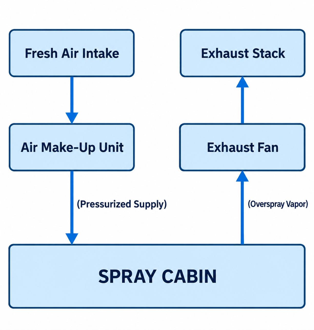
Diagram description
- Fresh Air Intake
- Air Make-Up Unit
- (Pressurized Supply)
- SPRAY CABIN
- (Overspray Vapor)
- Exhaust Fan
- Exhaust Stack
- Fresh Air Intake → Air Make-Up Unit
- Air Make-Up Unit → SPRAY CABIN: (Pressurized Supply)
- SPRAY CABIN → Exhaust Fan: (Overspray Vapor)
- Exhaust Fan → Exhaust Stack
- Fresh Air Intake → Air Make-Up Unit → SPRAY CABIN, second edge qualified Pressurized Supply.
- SPRAY CABIN → Exhaust Fan → Exhaust Stack, first edge qualified Overspray Vapor.
- Supply left downward; exhaust right upward.
Code Compliance and Approval Boundaries
Purchasing an industrial spray booth built to NFPA or OSHA design specifications does not instantly grant local compliance.
Equipment manufacturers supply engineered hardware, structural panel sets, and electrical drawings that meet industry standards. However, identify the applicable approvals with your Authority Having Jurisdiction (AHJ) and responsible project professionals. Review items such as:
- Proper integration of an approved fire suppression system (dry-chemical, water spray, or gaseous).
- Required airflow-proving, spray-prevention, and fire-protection interfaces under the approved design.
- Approved roof penetrations and property-line setbacks for exhaust emissions.
Evaluate Proposals, Lifecycle Costs, and Project Scope
When reviewing equipment proposals, comparing total prices alone is misleading. One supplier may quote an unpressurized bare shell with loose components, while another quotes an integrated system with balanced air-handling equipment and controls.
| Component / Scope Item | Low-Bid Proposal | Comprehensive System |
|---|---|---|
| Cabin Walls & Doors | 18-ga single-skin | 18-ga double-wall ins. |
| Lighting Fixtures | Standard T8 / loose | Sealed, pre-wired LED |
| Intake Filtration | None / Basic mesh | Diffusion ceiling |
| Exhaust Duct Package | Excluded | Duct, cap, cleanouts |
| Air Make-Up Unit (AMU) | Excluded | Direct-gas, interlock |
| Variable Speed Drives (VFD) | Excluded | Energy-saving idle/run |
| Technical Factory Drawings | Basic layout | Confirm required approvals |
The Real Cost of Excluded Scope
Examine every proposal line by line to determine what is included in the crate and what must be sourced through local mechanical or electrical trades:
- Duct packages and dampers: Does the quote include the vertical exhaust duct, weather-proof roof penetration curb, cleanout doors, and automatic backdraft dampers? Confirm the complete duct scope, appropriate construction, and installation cost rather than assuming it is included.
- Control integration: Does the package include a unified, listed control panel with pre-wired motor starters, lighting relays, and safety interlocks, or are you responsible for engineering controls on-site?
- Hardware ratings: Inspect the panel specifications. Compare panel construction, assembly requirements, and any documented insulation or acoustic performance rather than assuming a panel type establishes overall quality.
Long-Term Operational and Consumable Costs
Operating expenses can materially affect lifetime cost alongside the initial purchase. When comparing quotes, consider ongoing operating assumptions:
- Filter consumption: Review filter stages and pricing. A system that uses non-standard, proprietary filter sizes locks you into single-source replacement schedules. Check compatible filter availability, replacement specifications, and prices.
- Maintenance and diagnostics: When troubleshooting pressure drops or motor vibration, systems with built-in differential pressure gauges (manometers) allow clear, qualified diagnosis. Technicians can address real issues—such as saturated filters or slipped fan belts—instead of mistakenly attributing process failures to equipment age.
- Energy conservation: Look for airflow controls that adjust fan speeds based on gun usage. Idle modes lower fan RPM when an operator is masking or handling parts, cutting electricity costs and preventing the loss of treated shop air.
Capital Planning and Next Steps
Once you define your clear interior dimensions, airflow type, heating needs, and utility infrastructure, explore structured paint booth financing options through commercial equipment lenders. Compare written lender terms, upfront cash requirements, total payments, and excluded project costs against your working-capital needs.
Gather your dimensional drawings, coating data sheets, and facility utility limits into a single document. With these details verified, you can submit a clear enquiry and request a project quote with clearly defined equipment and site-work questions.
Sources
- https://www.paintbooth.com/how-to-choose-the-right-size-paint-booth-for-your-operations/
- https://www.paintbooth.com/what-are-the-differences-between-open-face-downdraft-and-crossdraft-paint-booths/
- https://www.paintbooth.com/what-utilities-do-you-need-before-installing-a-paint-booth/
- https://www.paintbooth.com/can-you-finance-a-paint-booth-and-what-are-options/
- https://globalfinishing.com/wp-content/uploads/2023/11/General_Industrial_Booth_Owner_Manual.pdf
- https://www.osha.gov/laws-regs/regulations/standardnumber/1910/1910.107
- https://www.paintbooth.com/quote/