
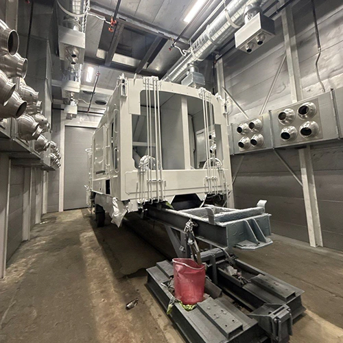
Surface defects destroy shop throughput and inflate material costs. When clearcoat emerges with pronounced texture, cratering, or an under-cured film, the immediate temptation is to start turning air regulator knobs, swapping reducers, or blaming the spray booth exhaust filters.
Random adjustments rarely solve paint defects. More often, they introduce secondary variables that obscure the real source. Systematically improving finish quality requires treating every defect as physical evidence: capture its visual structure, identify precisely when and where it appeared, cross-reference the coating technical data sheet (TDS), and isolate whether the breakdown happened during preparation, application, or booth operation.
Capture Defect Morphology and Preserve the Job Evidence
Before wiping down, sanding, or clearing a compromised panel, document the exact physical characteristics of the failure. Once a surface is abraded or stripped, the forensic trail is lost.
DEFECT EVIDENCE LOG
- Stage Detected
- [ ] Basecoat Flash [ ] Clear Wet Laydown [ ] Post-Bake
- Spatial Distribution
- [ ] Single Panel [ ] Leading Edges [ ] Entire Job
- Component Geometry
- [ ] Horizontal Only [ ] Vertical Only [ ] Substrate-Spec
- Job Metadata
- Ambient Temp / RH: ____________ Gun Setup: ______________
- Material Tracking
- Base Batch: ________ Clear Batch: ________ Hardener: ____
1. Macro Visual Inspection
Photograph the defect under direct and diffuse light before touching the panel. Note whether the blemish is a void, a raised particle, or a continuous surface irregularity:
- Craters and depressions: Look for round, bowl-shaped indentations with or without a raised center pin or droplet.
- Irregular surface profile: Check whether the film mimics the dimpled skin of a citrus fruit or shows distinct dry-spray wave patterns across the spray stroke pattern.
- Film stability issues: Observe whether the clearcoat shows soft spots, imprint marks, solvent bubbling, or persistent tackiness long after the prescribed cure cycle.
2. Process Timing
Pinpoint the exact process window where the defect became visible:
- Did the blemish appear during basecoat flash, immediately upon clearcoat wet-out, or only after the heat cycle?
- Defects visible in the wet film immediately behind the gun path make fluid delivery, application setup and contamination useful investigation categories; timing alone does not identify the cause.
- Defects that manifest only during the bake or cool-down cycle frequently involve solvent evacuation, flash timing, or thermal ramp rates.
3. Spatial Mapping
Map the location across the vehicle or batch.
- Is the issue isolated to a single plastic bumper cover, or does it cross metal body panels equally?
- Is it concentrated on horizontal top surfaces (hood, roof, decklid) where gravity causes falling debris to settle, or does it follow vertical spray paths?
- If identical defects occur on the lower rocker panels of every vehicle regardless of painter, check booth draft patterns near the floor extraction or prep handoffs.
4. Job and Chemistry Metadata
Record the exact product codes, hardeners, and solvent reducers used, including batch and lot numbers stamped on the cans. Note the cabin temperature and relative humidity displayed by the booth control panel during both application and cure cycles. Finally, retrieve the job record from the last fully accepted run sprayed with the same product line to compare recorded booth cycles and environmental conditions.
Separating Contamination, Texture, and Drying Failures
Finish problems fall into three distinct operational families: surface contamination, fluid dynamics/atomization, and solvent release/curing kinetics. Treating a texture issue like a contamination problem will only waste time and material.
Contamination and Crater Morphology
Craters, edge pull-backs, and fisheyes occur when a liquid coating encounters a localized area of low surface energy. The wet paint film cannot wet out over the contaminant, pulling away to form a distinct rim.
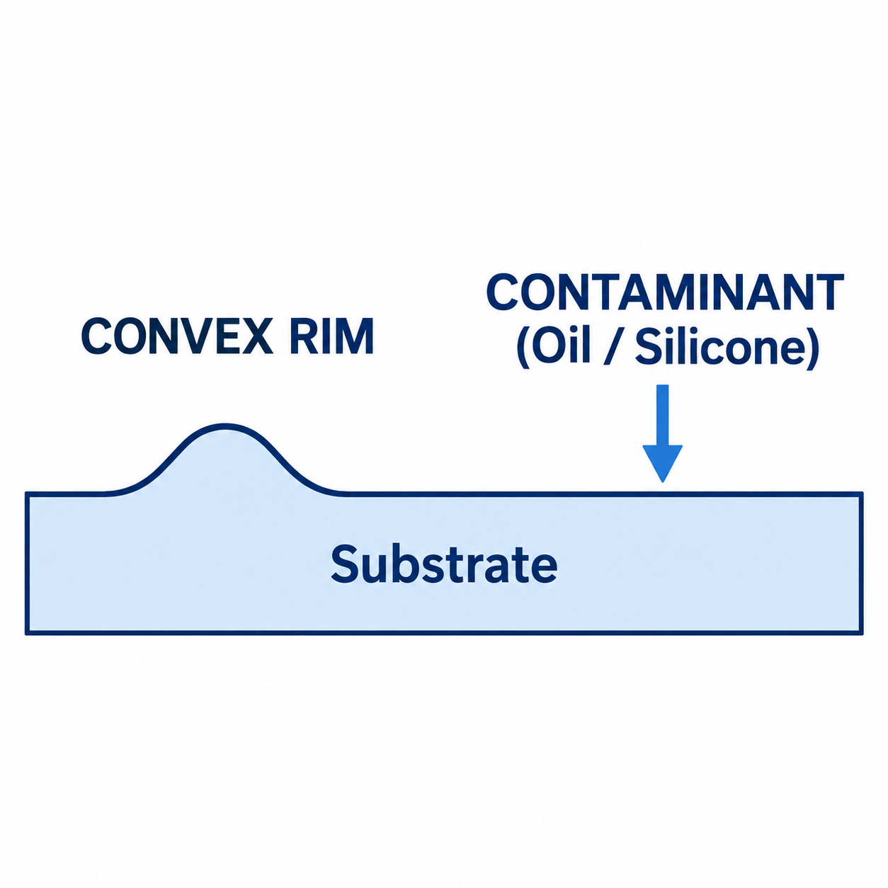
Diagram description
- CONVEX RIM
- CONTAMINANT (Oil / Silicone)
- Substrate
- Horizontal Substrate baseline has a smooth upward convex rim bump near left labelled CONVEX RIM above
- CONTAMINANT (Oil / Silicone) above flat baseline to right points downward at flat baseline
- Substrate
- CONVEX RIM
- CONTAMINANT (Oil / Silicone)
- Substrate versus airborne vectors: True fisheyes typically stem from surface contaminants—such as silicone lubricants, waxes, tire dressings, or residual release agents—that were not removed prior to spraying. Review standard fisheye defect guidance before making operational assumptions; craters do not inherently prove that the paint booth cabin has failed.
- Air line contamination: Contaminated compressed-air lines can contribute to finish defects. Record the affected panels and timing rather than assuming a uniform pattern proves an air-line fault.
- Prep handoff gaps: Contamination frequently rides into the cabin directly on the vehicle itself. Gaps in wiping protocols, contaminated tack rags, or airborne dust drifting from nearby prep bays break the barrier between the prep stall and the booth. Ensure technicians review vehicle preparation guidance and complete thorough vehicle preparation before booth entry rather than using the booth cabin as a secondary cleaning station.
Film Texture and Flow Irregularities
Texture defects represent a mechanical failure of the wet paint film to level before the solvents evaporate and viscosity rises beyond the point of flow.
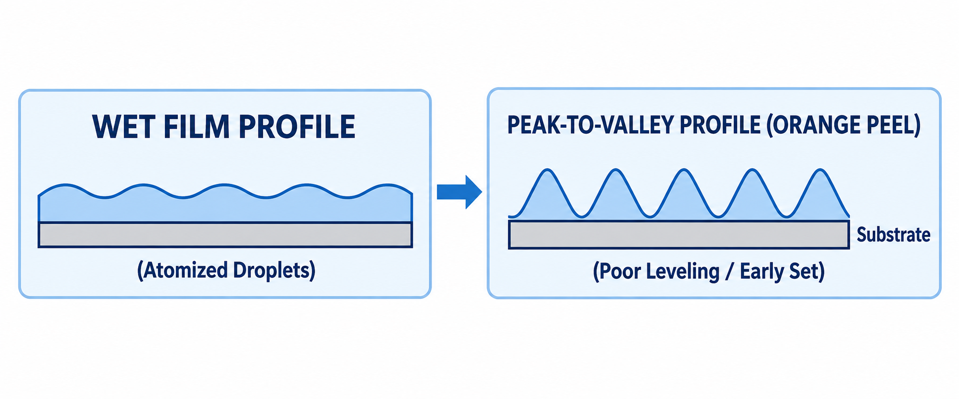
Diagram description
- WET FILM PROFILE
- (Atomized Droplets)
- PEAK-TO-VALLEY PROFILE (ORANGE PEEL)
- (Poor Leveling / Early Set)
- Substrate
- WET FILM PROFILE → PEAK-TO-VALLEY PROFILE (ORANGE PEEL): profile transition
- WET FILM PROFILE → (Atomized Droplets): qualifier
- PEAK-TO-VALLEY PROFILE (ORANGE PEEL) → (Poor Leveling / Early Set): qualifier
- Two surface profiles side by side connected by rightward transition arrow.
- WET FILM PROFILE has wavy film over substrate with Atomized Droplets qualifier below.
- PEAK-TO-VALLEY PROFILE (ORANGE PEEL) has repeated pointed peaks over same baseline, Substrate label at baseline right, Poor Leveling / Early Set qualifier below.
- No quantitative axes.
- Droplet size and atomization energy: Insufficient air pressure at the spray gun cap prevents the fluid stream from shearing into fine, uniform droplets. Coarse droplets land on the surface and resist coalescing into an unbroken, flat film.
- Solvent evaporation rates: If a fast-evaporating reducer is sprayed into an environment that is too warm, solvent leaves the atomized droplet in flight. The droplet reaches the panel with too much viscosity to flow, freezing orange peel into the surface. Consult published orange peel guidance to verify that component selection aligns with current cabin conditions.
- Distance and spray pattern: Spraying too far from the substrate, moving the gun too rapidly, or holding an excessive standoff distance forces paint droplets to partially dry before impact. Conversely, excessive fluid delivery without corresponding atomization air leads to heavy, sagging waves.
Retarded Cure and Slow Drying
Slow drying occurs when the cross-linking reaction is chemically starved, physically suppressed by trapped solvents, or starved of adequate thermal and volumetric air energy.
| Probable Cause | Diagnostic Observation |
|---|---|
| Excess Film Build | Soft under-film; top skin seals before lower solvents escape. |
| Chemistry Mismatch | Wrong hardener ratio or temperature-incompatible activator. |
| Stagnant Airflow | Review airflow evidence alongside product drying requirements. |
| Thermal Deficit | Metal substrate fails to reach target soak temperature. |
- Film thickness over-application: Clearcoats applied in excessively heavy coats trap fast solvents under a skinned surface layer. The surface may feel dry to a light touch, but the underlying film remains soft and easily marred.
- Chemistry and mixing accuracy: Inappropriate component selection or incorrect mixing can affect drying and curing; compare the actual formulation and conditions with the product data sheet. Review the material's specific slow-drying guidance to evaluate how ambient shifts impact pot life and cure rates.
- Booth environmental conditions: Check whether the actual product data sheet specifies air temperature, substrate temperature or another condition for its drying schedule. Insufficient airflow can contribute to slow drying, but the observed defect does not establish an airflow fault without further evidence.
Audit Documented Process Variables Before Modifying Equipment
When a defect trend emerges, verify documented process variables against technical literature before reconfiguring booth mechanicals or air balancing dampers.
DIAGNOSTIC PROCESS AUDIT GATE
- Step 1: Material Verification
- Cross-reference Product Data Sheet (PDS) for mix ratio & hardener selection.
- Verify gun cap, fluid tip sizing, and dynamic inlet air pressure.
- Step 2: Compressed Air Delivery
- Inspect point-of-use coalescing filters for oil or water blow-by.
- Arrange a supplier-approved air-quality check at the point of use.
- Step 3: Booth Operational Health
- Log differential pressure gauges (manometer / Magnehelic).
- Verify intake and exhaust filter loading and perimeter seal integrity.
Technical Data Sheet (PDS) Compliance
Every refinish product relies on a distinct rheology curve. Pull the active PDS for the exact clearcoat or basecoat in use. Verify:
- Specified fluid tip orifice size (e.g., 1.2 mm vs. 1.4 mm).
- Dynamic inlet operating pressure measured at the gun handle with the trigger fully pulled.
- Required flash-off times between coats. Shorting flash times to accelerate cycle times is a primary cause of solvent pop and clouding.
Compressed Air Supply Quality
Air entering the spray gun must meet the coating and equipment requirements. Review point-of-use filtration and air-system maintenance records, and arrange a supplier-approved air-quality check. If contamination is detected, have qualified personnel identify the affected component before prescribing service.
Cabin Operating Environment
A spray booth is an engineered air-handling enclosure designed to contain overspray and sweep away volatile vapors. Do not jump to the conclusion that finish quality alone indicates a broken exhaust system. Instead, review mechanical baselines:
- Differential pressure tracking: Check each gauge against its documented purpose and equipment-specific baseline. Filter differential pressure and cabin pressure are different measurements; record which quantity is being observed before drawing conclusions about loading or air balance.
- Filter seat and condition: Inspect intake ceiling media and exhaust arrestors. Ensure filters sit flat in their tracks with no curled edges, gaps, or collapsed media frames. Follow the booth builder's manufacturer maintenance instructions and adhere to routine paint booth filter maintenance schedules based on measured resistance rather than visual guesswork.
- Visual clarity: Substandard lighting obscures wet-edge tracking and fluid laydown, forcing painters to guess on film build. If shadows or low-CRI fixtures compromise wet-film visibility, consider planning an LED lighting upgrade based on the visibility problem and fixture compatibility.
Tracking these baseline operational factors is critical to reducing paint waste, since re-spraying jobs consumes billable hours, burns paint volume, and occupies cabin cycle time that should be generating revenue.
Verify Corrective Actions on Comparable Work
Changing several things at once makes it harder to identify which change affected the result. When testing a corrective theory, isolate a single operational variable and run an empirical trial.
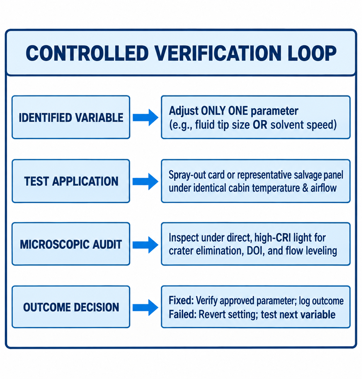
Diagram description
- CONTROLLED VERIFICATION LOOP
- IDENTIFIED VARIABLE
- Adjust ONLY ONE parameter
- (e.g., fluid tip size OR solvent speed)
- TEST APPLICATION
- Spray-out card or representative salvage panel
- under identical cabin temperature & airflow
- MICROSCOPIC AUDIT
- Inspect under direct, high-CRI light for
- crater elimination, DOI, and flow leveling
- OUTCOME DECISION
- Fixed: Verify approved parameter; log outcome
- Failed: Revert setting; test next variable
- IDENTIFIED VARIABLE → Adjust ONLY ONE parameter
- TEST APPLICATION → Spray-out card or representative salvage panel
- MICROSCOPIC AUDIT → Inspect under direct, high-CRI light for
- OUTCOME DECISION → Fixed: Verify approved parameter; log outcome
- OUTCOME DECISION → Failed: Revert setting; test next variable
- Outer CONTROLLED VERIFICATION LOOP box; four rows, each left label points RIGHT to its associated description.
- IDENTIFIED VARIABLE → Adjust ONLY ONE parameter with (e.g., fluid tip size OR solvent speed).
- TEST APPLICATION → Spray-out card or representative salvage panel with under identical cabin temperature & airflow.
- MICROSCOPIC AUDIT → Inspect under direct, high-CRI light for with crater elimination, DOI, and flow leveling.
- OUTCOME DECISION → two text outcomes Fixed: Verify approved parameter; log outcome and Failed: Revert setting; test next variable.
- Formulate a narrow hypothesis: For a texture defect, select one investigation variable supported by the product and gun documentation. Any pressure or component change must remain within the approved application instructions.
- Execute on a test panel: Spray a dedicated test card or a salvage panel staged inside the cabin under identical temperature, airflow, and flash cycles as the failed production run.
- Inspect the outcome systematically: Evaluate the test panel after complete cure. Measure film build with a dry film thickness (DFT) gauge to verify that application thickness matches the product specification.
- Confirm rework pathways with the material manufacturer: When dealing with production work that has already failed, consult the coating supplier’s technical representative or product technical manual before initiating repairs. The coating manufacturer determines rework eligibility—including minimum cure intervals before topcoating, recoat adhesion windows, and whether a film must be mechanically stripped or can simply be scuffed and re-cleared. Generic polishing or aggressive sanding can compromise cross-coat adhesion or void manufacturer paint performance warranties.
Equipment Support and Parts Sourcing
When structured diagnostics point to an equipment limitation—such as degraded exhaust holding frames, compromised door perimeter seals, failing intake diffusers, or airflow imbalances that filter swaps cannot resolve—replace the affected hardware with exact-specification components.
To discuss filters, replacement door seals or other hardware for your cabin configuration, submit an equipment inquiry:
Provide your booth manufacturer, cabin model, interior dimensions, airflow type (crossdraft, semi-downdraft, or full downdraft), and the specific components under review. Accurate equipment details help a supplier assess compatibility; airflow performance and compliance require review of the complete installed system.