
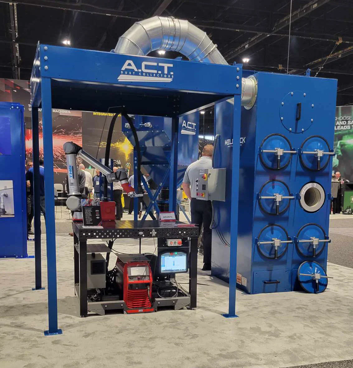
Robotic welding cells generate continuous, high-volume thermal plumes within a confined footprint. While the welding torch follows an identical path on every cycle, the rising fume plume rarely behaves with the same mechanical consistency. Drafts from overhead plant doors, heat buildup around large fixtures, and the swinging arc of index tables continuously redirect particulate away from static extraction points.
Choosing an extraction strategy requires balancing localized, unit-level capture against larger facility air-handling infrastructure. A compact, cell-side collector can offer clean routing and independent control, but it cannot overcome an inadequate hood geometry or a miscalculated static pressure load. Determining whether a dedicated unit fits your cell requires examining capture mechanics, cell workflow, and real operating limits.
Cell Capture Mechanics: Why Repetition Does Not Equal Stability
A robotic arm executes the exact same weld schedule cycle after cycle, but plume dynamics change constantly.
Thermal buoyancy drives welding fume upward, while weldment heating and surrounding drafts can alter the plume. Capture must be evaluated across the actual weld path and operating conditions rather than a generic velocity range.
- Buoyant fume rises from the changing weld location.
- Plant drafts, fixtures, and part motion can redirect it outside a partial hood.
- Verify capture through the actual approved cell cycle.
Enclosure geometry determines whether that fume reaches your collector or escapes into the ambient plant:
- Part Positioners and Trunnions: A two-station rotating table swings a finished part out for operator unloading while indexing a cold assembly into the torch envelope. The hood must account for changing arc locations across the entire fixture span, not just a single sweet spot.
- Loading Clearances: Overhead cranes and gantry loaders demand open-top enclosures. When the top of the cell must remain open for rigging, hood and enclosure options must be evaluated around rigging access; an open top does not establish one mandatory extraction design.
- Access Doors and Curtain Gaps: Strip curtains and interlocked sliding doors create varying intake profiles. If an access opening changes during an approved operating sequence, the sudden drop in face velocity can spill accumulated fume directly into the breathing zone.
Placing a high-efficiency collector next to a robotic station does not guarantee clean air. The collector provides negative pressure and filtration, but the hood, side baffles, and cell enclosure do the physical work of entraining the smoke.
Compact Cartridge Units: The Dedicated Collector Archetype
A compact cartridge collector mounts immediately adjacent to or on top of the robotic cell, where its installation and structural requirements permit, providing dedicated air handling.
The legacy WeldPak article name should not be treated as a current model specification. As a current manufacturer example, ACT’s WeldPack 4 product information describes a purpose-built design: an integrated spark trap, a compact cartridge system, and a small overall footprint designed to pull air directly from automated welding enclosures.
- Current ACT WeldPack 4 example: integrated inlet spark trap, cartridge collection, enclosed fan, and controls.
- Hood, duct, discharge, and air-return decisions remain part of the complete engineered installation.
These compact setups serve a specific operational niche within modern cartridge dust collectors:
- Direct Coupled Ducting: By sitting within feet of the hood pickup, duct runs remain short. This minimizes static pressure losses through friction, reduces material buildup inside horizontal ducting, and can reduce the resistance that the selected fan must overcome.
- Integrated Spark Management: Because the distance between arc and filter media is compressed, robust pre-separation is non-negotiable. Compact units rely on integrated mechanical baffles or drop-out chambers to knock down hot, coarse spatter before it contacts the filter media.
- Modular Cell Relocation: When lean manufacturing layouts shift, a cell with an integrated, dedicated collector moves as a self-contained asset. Central branch work may be reduced, but relocation still requires installation and performance re-verification.
However, a compact footprint forces physical trade-offs. Dust holding capacity is limited, filter area is condensed, and maintenance access requires clear plant floor space immediately around the cell perimeter.
Sizing the Entire Air Path: Hood, Duct, Fan, and Access
A collector cannot be specified by quoting cell square footage or counting robot arms. The fan, hood design, and filter media must form an engineered match.
- Capture hood: geometry, proximity, and operating access.
- Duct network: transport conditions and resistance.
- Filter system: compatible media, loading, and maintenance.
- Fan: performance against the complete clean and loaded system resistance.
Hood Design and Face Velocity
Capture velocity must overcome room drafts at the furthest point of torch travel. The required capture arrangement and airflow depend on hood geometry, weld locations, drafts, and applicable requirements; open-panel area alone does not supply a universal target.
Duct Routing and Transport Velocity
To prevent dry welding particulate from settling in horizontal runs, select duct transport conditions for the actual fume, loading, routing, and design requirements. Undersized ducts cause high static friction loss, choking airflow; oversized ducts drop the air speed below transport velocity, causing particulate to fall out, clog duct runs, and create a persistent fire hazard.
Total System Resistance
Cartridge media, clean and loaded, adds resistance. Adding an integrated spark baffle, elbows, silencers, and discharge dampers directly increases static pressure requirements. Sizing a fan motor requires calculating this cumulative total system resistance, not just free-air fan ratings.
Operational and Regulatory Verification
Verifying performance requires testing the capture zone under full operating conditions. Relying solely on the presence of automated machinery does not satisfy compliance.
Under OSHA’s welding ventilation provisions, ventilation and exposure control obligations remain anchored to the base metals, flux components, coatings, and room volume involved. Shielding gas flow, oil coatings on stamped parts, and continuous arc time can drive worker exposure beyond allowable limits if the capture mechanism spills particulate.
| Engineering Factor | Dedicated Compact Collector | Central Multi-Cell System |
|---|---|---|
| Duct Infrastructure | Minimal; straight, short runs directly to cell | Extensive; balanced mains, blast gates, long horizontal runs |
| Footprint Impact | Consumes valuable cell-side manufacturing floor space | Centralized outdoors, on a mezzanine, or in an equipment bay |
| Energy Consumption | Approved controls can match collector operation to cell needs, including any required run-on | Controls must suit connected-cell demand; a VFD is one possible strategy |
| Cross-Contamination | Isolated to single cell materials | Blends particulate from across multiple process lines |
| Failure Scope | Maintenance affects only that specific welding station | Collector maintenance or shutdown impacts all connected cells |
When a Dedicated Collector Falls Short
While compact units excel in standalone cells, certain operational conditions demand central industrial dust collection systems or engineered process modifications.
Multi-Process or Oily Feedstocks
Robotic cells processing parts coated with stamping lubricants, rust preventatives, or light anti-spatter oils present a dual-phase problem. Condensed oil vapors blind dry cartridge media rapidly, causing premature static pressure spikes that pulse-jet cleaning cannot clear.
Evaluating dust and mist collector differences becomes essential when oil aerosols accompany dry welding smoke; mixed loads require manufacturer review of compatible media, pre-separation, fire controls, and maintenance; do not prescribe a generic liquid-wash or coalescing retrofit.
- Welding fume mixed with oil aerosol may be incompatible with a selected dry cartridge system.
- Assess the actual fluid, particulate, heat, and spark profile with the manufacturer before selecting stages or modifying equipment.
Heavy Loading and High Deposition
High-amperage sub-arc processes or tandem-wire GMAW operations run high deposition rates with long arc-on times. Small hoppers on compact collectors fill quickly, and loading and cleaning duty can affect service life. Heavy-deposition lines may need greater holding capacity or a different collection arrangement; discharge design follows the process and system requirements.
Combustible Dust and Reactive Metallurgy
Grinding dust or reactive materials can require a combustible-dust assessment. Material identity alone does not establish the collected fume’s explosibility; required prevention, protection, and isolation follow the actual hazard assessment and applicable requirements.
Building a Cell-Specific Selection Packet
Before committing to a hardware design, build an engineering selection packet that defines the physical, mechanical, and material profile of the automated process.
1. Cell Envelope and Access Geometry
- Dimensional drawings showing the robot reach, fixture clearances, and part rotation bounds.
- Enclosure details: fixed walls, flexible curtains, interlocked service doors, and ceiling open areas for crane pick access.
- Physical clearances around the cell exterior, including overhead crane paths, forklift corridors, and maintenance access space for filter replacement.
2. Welding Schedule and Chemistry
- Process type: GMAW, FCAW, GTAW, or submerged arc.
- Arc-on time percentage per cycle and projected parts per shift.
- Safety Data Sheets (SDS) for wire consumables, base materials, and part surface coatings (such as galvanneal, primers, or rust-inhibiting oils).
- Presence of hexavalent chromium, manganese, or nickel, whose applicable exposure limits and controls must be assessed; filter efficiency alone does not establish acceptable exposure.
- Combine weld schedule and material data with cell geometry, facility constraints, and air-return requirements in the selection packet.
3. Plant Integration and Air Return Policies
- Exhaust destination: returning filtered air into the plant environment versus ducting through an exterior penetration.
- Compressed air availability, line pressure, and moisture quality at the cell drop for filter pulse-cleaning mechanisms.
- Cell control interfaces: tying collector start/stop commands directly to the robot safety circuit or weld controller.
Sharing these exact process variables allows technical teams to size face velocities, balance static pressure drops, and determine whether a compact unit or an engineered central network is the correct design path. To review your cell layout, material data, and duct velocity requirements, talk with a finishing systems specialist.