
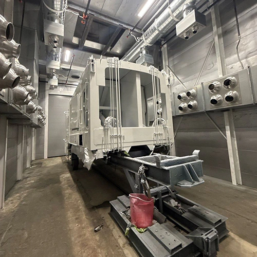
Soundproofing an industrial sandblasting booth requires treating acoustic paths without degrading containment, ventilation, or visibility. Blasting can generate high sound levels and transmit noise through walls, openings, ducts, and shared structures. Assess the actual sources and paths before defining the retrofit.
Lowering surrounding shop noise involves systematically mapping sound sources, separating boundary isolation from internal absorption, engineering modifications that endure harsh abrasive impact, and verifying real-world shift exposures under operating production cycles.
Baseline Acoustic Assessment: Sources, Paths, and Exposures
An effective noise mitigation plan starts with an empirical acoustic survey rather than assumed panel specifications. Blast room sound fields consist of multiple distinct mechanical and aerodynamic sources operating across disparate frequency bands.
| BLAST BOOTH SOUND FIELD | Path to Assess |
|---|---|
| Nozzle Jet, Substrate Hit, Media Rebound | Booth panels, openings, and internal reflections |
| Dust Collector & Fan | Ductwork, equipment supports, and discharge |
| Shared Floor and Structures | Flanking paths toward adjacent workstations |
| Doors / Seals | Airborne leaks toward aisles and other work areas |
Noise Sources Inside and Outside the Enclosure
A comprehensive baseline isolates each contributor across production states:
- Abrasive Nozzle Discharge: Compressed air leaving the nozzle creates jet noise. Measure its level and frequency content under the actual production conditions.
- Substrate Impact and Rebound: Structural ringing and deflection occur as media strikes the workpiece, generating broadband impact energy influenced by workpiece thickness, geometry, and material composition.
- Ventilation and Dust Collection: The continuous movement of air through makeup air louvers, blast room exhaust plenums, duct transitions, and the reverse-pulse cleaning mechanism of the dust collector generates low-to-mid-frequency aerodynamic rumble and mechanical blower noise.
- Abrasive Recovery Systems: Underfloor screw conveyors, bucket elevators, vibratory floors, and pneumatic floor recovery systems introduce structural vibration and continuous mechanical cycling noise.
Transmission Paths
Acoustic energy escapes the enclosure along three primary paths:
- Direct Airborne Transmission: Sound radiates directly through booth wall panels, ceiling assemblies, access doors, drive-in blast doors, and operator inspection windows.
- Flanking Transmission: Unmitigated mechanical energy bypasses the primary booth envelope through shared concrete slabs, structural steel supports, unisolated conduit, and rigid ductwork penetrations.
- Aperture Leaks: Unsealed door perimeters, worn bottom sweeps, cable entry glands, and makeup air openings allow high-frequency sound to escape through line-of-sight gaps.
Operating States and Exposed Personnel
A site survey should document relevant operating states, including background, ventilation and support equipment, active production blasting, and intermittent events. Choose representative states with the production and EHS teams rather than creating artificial or unauthorized test conditions.
Map these states against affected personnel groups. External fabricators, forklift operators, and assembly technicians may experience continuous or intermittent exposure, while the operator inside the booth experiences a different sound field. Spot measurements help locate weak points; exposure assessment must also account for worker locations and duration. Use representative personal sampling where area monitoring is inadequate, as required by 1910.95(d). For exposure dynamics and published benchmarks, consult sandblasting noise levels and exposure.
Regulatory Framework: Exposure Limits vs. Boundary Sound Levels
Plant managers must distinguish between regulatory employee exposure criteria and external acoustic design targets for enclosure boundaries.
Under OSHA’s occupational noise standard (29 CFR 1910.95), regulatory enforcement centers on personal worker exposure over time:
- Action Level (85 dBA 8-Hour TWA): Triggers mandatory implementation of a continuous hearing conservation program, including baseline and annual audiometric testing, employee training, and the availability of hearing protection devices.
- Table G-16 Permissible Exposures: Includes 90 dBA for eight hours. When exposures exceed the table’s limits, feasible engineering or administrative controls are required. Where controls are insufficient, appropriate personal protection must be provided and used.
| 8-Hour Exposure Framework | Duties to Review |
|---|---|
| 85 dBA Action Level | Hearing conservation program; baseline and annual audiometry; training; hearing protection availability |
| Table G-16 permissible exposures, including 90 dBA for 8 hours | Feasible engineering or administrative controls when limits are exceeded; appropriate PPE where controls are insufficient |
External booth boundary levels do not establish personal shift TWA.
These are employee shift-exposure criteria, not equipment boundary standards. An 86 dBA wall reading does not establish a nearby worker’s TWA or a violation by itself. Evaluate the worker’s full exposure and the applicable program duties.
Conversely, maintaining an exterior wall boundary at 82 dBA does not eliminate the need for blast operator controls, as internal nozzle operators remain exposed to intense localized sound fields.
Acoustic retrofits address engineering controls at the source and path level. They operate alongside, but do not replace, mandatory personal safety duties: respiratory protection and breathing-air systems remain regulated independently of noise interventions.
Acoustic Control Mechanisms: Source, Barrier, and Absorption
Controlling blast room sound requires aligning the physical control mechanism with the specific energy path. OSHA’s guidance on industrial noise controls categorizes structural interventions into source reductions, transmission barriers, and sound absorption:
- Source Controls: Altering physical processes to generate less acoustic energy. Examples include optimizing nozzle designs to reduce turbulence, running supply compressors at tuned operating pressures, applying dynamic balancing to exhaust fan impellers, and installing vibration isolation mounts beneath drive motors.
- Transmission Barriers (Sound Isolation): Assemblies designed to reduce airborne transmission between spaces. Mass, stiffness, damping, decoupling, openings, and frequency all affect performance. Adding mass or decoupling panels may help, but neither prevents transmission completely.
- Absorption (Reverberation Control): Porous or resonant materials that convert acoustic energy into heat within a space. Absorption reduces the buildup of reflected reverberant energy inside the blast booth, which lowers the overall internal sound pressure field driving the walls. Absorption alone cannot block sound transmission through a wall if the assembly lacks mass or has unsealed air gaps.
The following matrix illustrates how each control mechanism applies to specific blast booth failure points:
| Acoustic Problem | Control Mechanism | Engineering Approach | Verification Evidence |
|---|---|---|---|
| High reverberant buildup inside the booth | Internal sound absorption | Install abrasion-resistant, baffled acoustic absorbers or protected perforated panels | Octave-band sound pressure reduction inside the booth; lower reverberation decay time (RT60) |
| High direct airborne leakage through room envelope | Transmission barrier (Mass & Decoupling) | Evaluate suitable barrier assemblies and structural decoupling | Relevant assembly test data and field measurements at agreed locations and frequencies |
| Line-of-sight sound leaks through air intake/exhaust | Attenuation / Silencing | Install reactive or dissipative duct silencers and acoustic makeup air baffles | Static pressure drop within fan tolerance; reduced breakout noise at discharge and intake louvers |
| Sound escaping access openings | Aperture sealing | Evaluate compatible gaskets, seals, and hardware while preserving egress and required airflow | Inspect seal condition and verify acoustic and containment performance |
| Structural rumble in adjacent plant zones | Vibration isolation (Flanking control) | Evaluate isolation of equipment frames and duct supports using the measured source and structure | Appropriate vibration measurements on equipment, slab, and framing |
Preserving Blast Room Function: Ventilation, Cleanability, and Durability
Adding soundproofing to an industrial blast room involves strict physical constraints. Retrofits that interfere with abrasive handling, visibility, or air containment will fail rapidly in production environments.
Blast-room wall assembly review
- Abrasive protection and liner durability
- Protected acoustic materials with demonstrated performance
- Dust ingress, cleanability, and fire suitability
- Structural support and transmission performance
Have the suppliers specify the assembly for the actual room and hazards.
Abrasive Resistance and Liner Selection
Unprotected acoustic materials may erode or load with dust when exposed to abrasive rebound. Evaluate durability and protection with the blast-equipment and acoustic suppliers.
- Hanging heavy-duty rubber curtains remains standard practice for protecting structural walls from abrasive erosion, but hanging curtains provide minimal low-frequency transmission loss on their own.
- If using absorption behind liners or protective facings, have the supplier verify acoustic performance, abrasion resistance, dust ingress, cleaning, and fire suitability for the assembly.
- Avoid dust-trapping configurations. Dust loading can impair acoustic performance and complicate cleaning or decontamination.
Ventilation and Airflow Compliance
Noise controls must preserve ventilation performance. Under OSHA’s abrasive blasting ventilation requirements in 1910.94(a), enclosure openings require continuous inward airflow during blasting, and the exhaust must promptly clear dust afterward. Verify these functions alongside the system’s specified operating criteria.
- Silencers and acoustic louvers installed on makeup air intakes and exhaust ductwork introduce air-path resistance.
- Evaluate silencers and baffles against the actual fan/system performance. Added resistance can reduce airflow, so confirm containment and clearance after modifications rather than assuming a universal velocity threshold.
- Select silencer locations and construction for the air stream’s dust loading, abrasion, cleaning access, and fire hazards. A layout suitable for clean exhaust may be unsuitable upstream of particulate collection.
Fire Safety, Egress, and Structural Integrity
Industrial acoustic materials installed on or within the booth must comply with local fire codes and industrial standards for flame spread and smoke development:
- Have the responsible fire/design professionals determine material and assembly requirements. A Class A surface-burning classification under ASTM E84 does not by itself establish that a material is noncombustible.
- Personnel access doors must maintain emergency egress function. Adding mass to doors or installing soundproof vestibules must never obstruct push-bar exit devices, latching mechanisms, or code-mandated clear exit widths.
- Heavy retrofits add substantial dead weight. Engineering calculations must verify that existing booth frames, structural purlins, and roof trusses can support the dead load of dense acoustic paneling and duct silencer housings.
Ensuring your facility layout, structural frame, and air systems can accommodate these physical demands is an integral part of confirming your operational indoor sandblasting readiness before starting structural work.
Defining the Engineering Retrofit Scope
A targeted acoustic retrofit focuses on the structural paths that leak the most sound per linear foot. Rather than replacing the entire enclosure, plant managers can target several high-impact retrofits:
1. Drive-In and Personnel Door Assemblies
Door assemblies may be significant leakage paths. Use the survey to decide whether they warrant priority:
- Evaluate improved door assemblies or damping against measured transmission, structural capacity, handling, and egress requirements.
- Evaluate perimeter seals and latching that reduce sound leaks without obstructing required airflow or exit operation.
- Consider compatible bottom seals where the floor, media handling, door movement, and access requirements permit them.
2. Intake and Exhaust Attenuation
Air openings require acoustic treatment that permits air passage while scattering and absorbing sound waves.
- Evaluate engineered intake silencers or acoustic baffles that preserve the required airflow and resist the actual environment.
- If duct breakout is a measured problem, evaluate suitable external treatment with the acoustic and ventilation designers, including fire, cleaning, and access constraints.
- Where exhaust fans discharge near the facility boundary, evaluate discharge silencers selected for minimal pressure loss.
Acoustic intake review: Air must pass through the chosen silencer or baffle arrangement without compromising containment or clearance. Verify acoustic benefit, resistance, durability, and cleaning access.
3. Wall Damping and Outer Barrier Cladding
Thin-gauge modular sheet metal walls amplify sound by vibrating like large speaker cones.
- Evaluate damping of flexible panels where measured vibration or resonance contributes materially to the noise.
- Evaluate independent barrier assemblies or decoupled panels where the structural, access, and ventilation constraints permit them. Have the designer specify construction and spacing.
If the existing enclosure or fan system cannot support a practical retrofit, compare the cost and verified performance of modifications with suitable sandblasting booth options. Request application-specific acoustic data, support scope, and acceptance criteria rather than assuming a new enclosure provides a predictable return.
Commissioning and Acceptance Verification
Commissioning confirms that the soundproofing package meets acoustic performance specifications without degrading process ventilation or plant safety. Complete verification testing across all pre-retrofit test locations under identical production conditions.
| ACOUSTIC COMMISSIONING CHECKLIST | Acceptance Evidence |
|---|---|
| Envelope Boundary Measurement | Agreed acoustic criteria at documented locations and operating states |
| Airflow / Clearance | Inward airflow at openings, prompt dust clearance, and system design criteria |
| Fan / System Pressure | Measurements within documented operating baselines |
| Door Sealing | Compatible seal operation, containment, and acoustic performance |
| Emergency Egress | Required doors and exit hardware operate freely |
| Worker Exposure | Appropriate representative assessment of affected employees |
1. Multi-State Acoustic Profiling
Have qualified personnel repeat measurements at the agreed baseline locations and operating states using suitable calibrated instruments. Record frequency data where needed to judge the control’s performance:
- State A: Facility background sound level (blast booth offline).
- State B: Booth ventilation system running alone.
- State C: Representative active production blasting using approved settings, workpieces, and media.
- State D: Relevant recovery, cleaning, or intermittent events that occur in normal approved operation.
Compare these results against the baseline survey to determine the real-world insertion loss achieved by the modifications across each frequency band.
2. Ventilation and Differential Pressure Balance
Verify that acoustic silencers and baffles have not compromised airflow:
- Verify inward airflow at openings, dust-clearance performance, and the system’s design criteria using appropriate measurements.
- Check collector and exhaust-system pressure against documented design and operating baselines. Confirm the fan and system operate within their specified conditions.
3. Shift Dosimetry Verification
Assess affected workers’ post-retrofit exposure using appropriate representative sampling over the workday. Use the findings to review hearing-conservation participation and protection requirements; include the operator and other affected personnel, not only adjacent workers.
Technical Data to Prepare for an Acoustic Solution
Procuring an engineered acoustic package requires providing manufacturers and acoustic engineers with precise facility data. Gathering this operational profile beforehand shortens engineering review cycles and avoids costly design modifications:
- Physical Enclosure Dimensions: Length, width, and height of the existing booth, including panel skin gauges, structural beam orientations, and foundation slab details.
- Abrasive Blasting Equipment Profiles: Operating blast pressure (PSI), nozzle orifice sizes, nozzle styles (e.g., venturi, wide-throat), media type and mesh size, and the maximum number of operators blasting simultaneously.
- Ventilation and Dust Collection Performance: Blower make and model, fan curves, operating CFM, design static pressure, duct diameters, and the physical routing of intake and discharge lines.
- Baseline Octave-Band Acoustic Data: Linear sound pressure levels measured from 31.5 Hz through 8,000 Hz at defined perimeter boundaries and adjacent workstation locations during active production.
- Facility Layout and Egress Constraints: Proximity of the blast booth to exterior property lines, plant offices, and nearby workstations, alongside paths of travel and emergency exit routes.
Compiling these variables helps define a reviewable acoustic scope. When you request a sandblasting booth quote, include the agreed noise, ventilation, structural, access, and production acceptance criteria so the proposed solution can be evaluated and commissioned against them.