
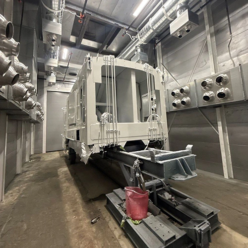
An industrial finishing line links material preparation, coating application, and final drying or cure. Raw fabrications or cast components may enter with soils and oxides, pass through chemical or mechanical preparation, and receive a liquid or powder layer selected for the required service conditions.
Equipment selection fails when shops buy individual machines in isolation. A high-efficiency spray booth cannot compensate for inadequate surface prep, nor can a convection oven cure a coating if the conveyor moves heavy parts out of the heated zone before the steel reaches its target temperature. Sizing an industrial finishing line requires working backward from the coating chemistry and the physical profile of the parts you produce.
Define the Part and the Coating Requirement Before Selecting Hardware
Equipment dimensions, utility capacities, and conveyor speeds depend on your part envelope and the coating's Technical Data Sheet (TDS). Documenting these parameters up front prevents expensive field modifications later.
PART & PROCESS PROFILE
- Substrate & Surface Metallurgy (CRS, HRS, Cast Iron, Al, Galvanized)
- Physical Envelope (Max / Min Dimensions: Length x Width x Height)
- Thermal Mass (Heaviest Part Weight, Cross-Sectional Thickness)
- Production Dynamics (Parts per Hang, Line Speed, Takt Time)
- Coating Parameters (Target DFT, Flash Time, PMT Soak Schedule)
1. Substrate and Metallurgy
The base metal dictates preparation chemistry, blast media, and oven heat absorption.
- Cold-rolled steel (CRS) presents relatively uniform surfaces with light protective oils.
- Hot-rolled steel (HRS) carries brittle mill scale that may need mechanical blasting or chemical descaling before coating.
- Aluminum forms natural self-passivating oxides that need preparation selected for the alloy and finish, which may include suitable cleaners and conversion coatings.
- Castings introduce porous structures that trap machining lubricants, water, and blast dust, often outgassing during oven cure cycles and causing pinholes in the cured finish.
2. Geometry, Mass, and Part Mix
Record the maximum and minimum dimensions (length, width, height) of every part planned for the line. Calculate the individual weight and cross-sectional thickness of the heaviest part. A light sheet metal assembly heats rapidly; a 2-inch-thick steel weldment acts as a thermal heat sink that absorbs massive thermal energy before its surface reaches cure temperature.
Your product mix determines the equipment profile:
- High-volume, low-mix operations favor continuous monorail or power-and-free overhead conveyors running through automated multi-stage washers, continuous spray zones, and tunnel ovens.
- Low-volume, high-mix operations with extreme swings in part geometry usually require batch cells: manual wash stations, walk-in application booths, and batch ovens with cart or roll-in track loading.
3. Finish and Performance Specifications
Corrosion and cosmetic demands govern your process sequence. A structural bracket destined for a dry equipment room might require only degreasing and a single coat of primer. An exterior architectural extrusion or agricultural chassis exposed to UV, salt, and gravel impact requires a finish system validated against the specified corrosion, weathering, and impact tests; ASTM B117 is a salt-spray test method, not a stand-alone service-life guarantee.
4. Coating Technical Data Sheet (TDS) Requirements
Obtain the TDS for every coating you intend to apply. Pull the following parameters directly from the manufacturer:
- Required surface cleanliness and profile: Target surface profile depth (mils/microns) and cleaning standard (e.g., SSPC-SP 10 / NACE No. 2 near-white blast).
- Application parameters: Recommended transfer method, atomization pressure, target dry film thickness (DFT), and minimum/maximum wet film thickness (WFT).
- Flash-off windows: Minimum and maximum time solvent-borne or waterborne wet films must stand before entering forced-draft heat.
- Cure window: Minimum Part Metal Temperature (PMT) and the duration the substrate—not merely the oven air—must maintain that temperature.
Choose Preparation and Cleaning Equipment
Coatings rely on molecular and mechanical adhesion to the substrate. If your cleaning system fails to remove incoming grease, rust, and particulates, the most advanced application booth will still yield blistering, flaking, and premature field corrosion.
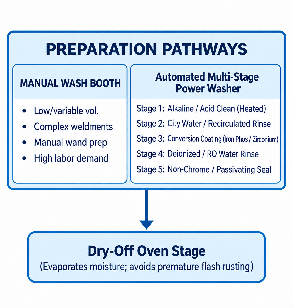
Diagram description
- PREPARATION PATHWAYS
- MANUAL WASH BOOTH
- Low/variable vol.
- Complex weldments
- Manual wand prep
- High labor demand
- Automated Multi-Stage Power Washer
- Stage 1: Alkaline / Acid Clean (Heated)
- Stage 2: City Water / Recirculated Rinse
- Stage 3: Conversion Coating (Iron Phos / Zirconium)
- Stage 4: Deionized / RO Water Rinse
- Stage 5: Non-Chrome / Passivating Seal
- Dry-Off Oven Stage
- (Evaporates moisture; avoids premature flash rusting)
- PREPARATION PATHWAYS → Dry-Off Oven Stage
- PREPARATION PATHWAYS → MANUAL WASH BOOTH: contains pathway
- PREPARATION PATHWAYS → Automated Multi-Stage Power Washer: contains pathway
- Pathway container points down to Dry-Off Oven Stage with qualifier Evaporates moisture; avoids premature flash rusting.
Incoming Contamination vs. Cleaning Methods
Identify all contaminants entering your facility:
- Heavy stamping compounds, drawing lubricants, and synthetic coolants call for a cleaning process matched to the soil and substrate; heated alkaline cleaning is one option.
- Laser scale, welding slag, and rust require abrasive blasting or chemical deoxidizers; standard detergent washes will not remove tightly bonded oxides.
- Shop dust, metal fines, and lint need removal without recontaminating the prepared surface.
Manual Wash Booths vs. Automated Pretreatment Washers
For low-volume or oversized parts that cannot run through a standard tunnel, wash booth equipment provides an enclosed environment with fluid containment, vapor exhaust, and manual spray wands. Operators control the exposure time and mechanical impingement, using the wash system’s specified tools and chemistry to apply cleaners, rinses, and any required treatments. Manual systems introduce human variability—such as missed pockets or uneven chemical dwell times—but offer low initial capital cost for high-mix lines.
Automated tunnel washers use spray risers and nozzles to deliver controlled chemical and rinse impingement as parts travel through on a conveyor. These systems deliver repeatable chemical exposure times, spray pressures, and bath temperatures. Multi-stage washers scale to the performance specification; these sequences are examples, not fixed requirements:
- 3-Stage Systems: Clean/phosphate combo, rinse, seal rinse. Common for moderate indoor service requirements on mild steel.
- 5-Stage Systems: Dedicated alkaline clean, rinse, iron phosphate or zirconium conversion coating, rinse, and deionized/seal rinse. One possible arrangement for industrial equipment.
- 7-Stage (or higher) Systems: May support multi-metal lines with additional cleaning, etching, or treatment steps selected for divergent surface chemistries.
The chemistry, stage count, and sequence must match your substrate and coating requirements; an automated multi-stage washer is not mandatory for every facility, but pretreatment before coating is essential to prevent bond failure.
Drying, Containment, and Waste Handling
Wetted parts exiting chemical wash stages must dry quickly to avoid flash rusting or water-spotting before application. Plan a drying step adequate to remove water from joints, seams, and blind pockets; confirm the method and equipment with the process supplier.
Every wash system generates process effluent. Evaluate regulatory and operational needs:
- Drainage and containment: Stainless steel or coated tanks, sloped floors, and chemical-resistant trenches.
- Filtration and maintenance: Oil coalescers, bag filters, and skim systems to extend wash bath longevity.
- Waste treatment: Municipal discharge limits and effluent composition determine treatment needs, which may include pH adjustment, metals removal, or sludge dewatering.
Connect Application Equipment to the Coating Process
Application hardware creates the controlled micro-environment where the coating meets the part. The enclosure must prevent external airborne shop dust from settling into wet or unfused coatings while capturing overspray to protect workers and maintain regulatory compliance.
APPLICATION ENVIRONMENT MATRIX
| PARAMETER | LIQUID COATING INTERFACE |
|---|---|
| Primary Contaminant | Wet overspray particulates & solvent VOCs |
| Exhaust Filtration | Multi-stage fiberglass/paper particulate pads |
| VOC Handling | Direct outside exhaust or thermal oxidizer |
| Relative Humidity (RH) | Tight control needed for waterborne flash |
| PARAMETER | POWDER COATING INTERFACE |
|---|---|
| Primary Contaminant | Dry, finely ground polymer dust |
| Exhaust Filtration | Cartridge filters / cyclone reclaim systems |
| VOC Handling | Negligible VOCs; air often recirculated |
| Relative Humidity (RH) | Product-specific RH window |
Liquid Spray vs. Powder Application Interfaces
Liquid and powder coating methods require fundamentally different containment systems:
- Liquid spray environments generate wet overspray and release volatile organic compounds (VOCs). They require constant, single-pass airflow to keep solvent concentrations well below lower explosive limits (LEL).
- Powder application environments handle dry polymer particulates. Airflow must prevent powder clouds from escaping the booth envelope while avoiding excessive draft velocities that disturb electrostatic powder transfer. Powder booths use recovery cyclones or cartridge filter banks to separate powder from the air, often returning conditioned air to the plant if permitted by safety standards.
Airflow Direction and Filtration
The primary objective of application ventilation and filtration is controlling particulate migration:
- Intake Filtration: Captures incoming facility dust, lint, and ambient shop contaminants before the air enters the application envelope.
- Exhaust Filtration: Traps paint overspray particles before air reaches exhaust fans and ductwork. Standard exhaust filters capture solid and liquid particulates; they do not remove solvent vapors or VOCs. Managing vapor requires direct-to-atmosphere exhaust stacks designed for proper dispersion or the addition of downstream thermal abatement systems.
Airflow layout within industrial paint booths includes these two common structural designs:
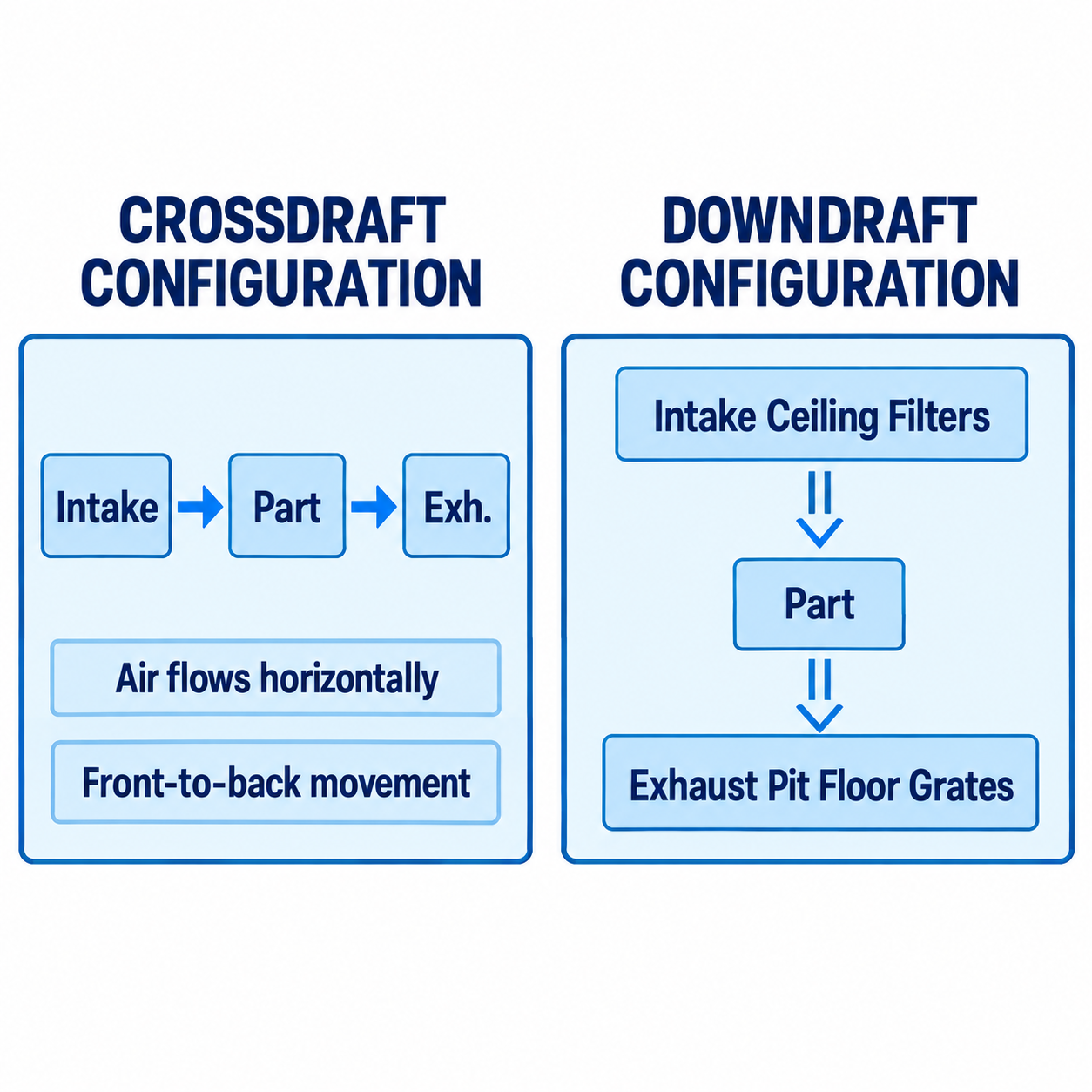
Diagram description
- CROSSDRAFT CONFIGURATION
- DOWNDRAFT CONFIGURATION
- Intake
- Part
- Exh.
- Air flows horizontally
- Front-to-back movement
- Intake Ceiling Filters
- Exhaust Pit Floor Grates
- Part
- Intake → Part
- Part → Exh.
- Intake Ceiling Filters → Part
- Part → Exhaust Pit Floor Grates
- CROSSDRAFT CONFIGURATION
- Intake
- Part
- Exh.
- Air flows horizontally
- Front-to-back movement
- DOWNDRAFT CONFIGURATION
- Intake Ceiling Filters
- Part
- Exhaust Pit Floor Grates
- Two separate enclosures side by side.
- Left title CROSSDRAFT CONFIGURATION; enclosed horizontal Intake → Part → Exh. with separate contained notes [Air flows horizontally] and [Front-to-back movement].
- Right title DOWNDRAFT CONFIGURATION; enclosed vertical Intake Ceiling Filters → Part → Exhaust Pit Floor Grates.
- Crossdraft: Moves air horizontally from the entry doors or front intake bank through the work zone and out the rear exhaust filter bank. While structurally simpler and avoiding floor pits or raised basements, overspray generated upstream travels across downstream parts unless parts are carefully positioned.
- Downdraft: Introduces filtered air across the entire ceiling and pulls it vertically downward through floor grating into exhaust trenches. This layout quickly clears overspray away from the part and the operator's breathing zone, reducing rework on horizontal surfaces.
Airflow direction alone does not guarantee a high-gloss, defect-free finish. Air speed, booth pressure balancing, gun atomization setup, electrostatic grounding, and cleaning discipline all contribute directly to transfer efficiency and cosmetic finish.
Plan Cure, Handling, and Utilities Together
Curing converts a fluid or powder layer into a tough polymer matrix. The greatest misconception in finishing system sizing is confusing oven setpoint temperature with the thermal experience of the part.
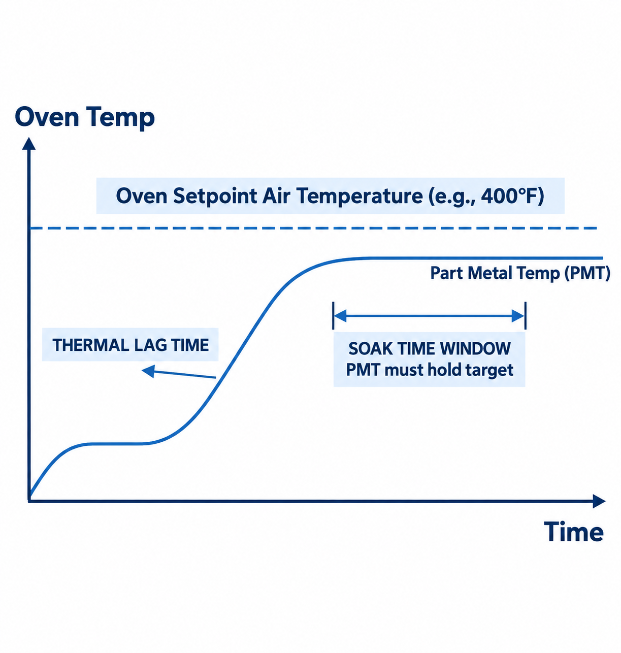
Diagram description
- Oven Temp
- Oven Setpoint Air Temperature (e.g., 400°F)
- Part Metal Temp (PMT)
- THERMAL LAG TIME
- SOAK TIME WINDOW
- PMT must hold target
- Time
- Chart y axis Oven Temp upward, x axis Time right.
- Horizontal Oven Setpoint Air Temperature (e.g., 400°F) above Part Metal Temp (PMT) curve.
- PMT starts low, rises briefly, low plateau, then rises gradually to plateau below oven setpoint.
- THERMAL LAG TIME arrow points left toward rising curve; SOAK TIME WINDOW and PMT must hold target below plateau.
- No numeric ticks.
- Oven Temp
- Time
Dry-Off vs. Final Cure
Treat dry-off and final cure as distinct process jobs, even when a suitably designed batch oven can serve both at different stages:
- Dry-off ovens use a process-specific drying cycle. Their role is vaporizing residual water from seams and blind holes following liquid pretreatment.
- drying and curing equipment for coatings operates on precise time-versus-temperature schedules dictated by polymer cross-linking chemistry.
Running wet parts directly into a high-temperature cure oven boils trapped wash water, popping wet paint skins, causing solvent boil, or creating steam pockets that bubble powder coatings before they can melt and flow.
The Physics of Cure: Part Metal Temperature (PMT)
A coating does not cure simply because the oven thermometer reads 400°F. The chemical reaction depends on the part temperature during cure.
When cold steel enters a continuous or batch oven, the metal absorbs convective and radiant energy from the air. For an illustrative timing calculation, suppose a thin part reaches a 375°F PMT in four minutes while a thick bracket takes eighteen minutes. These are assumed times, not predicted heat-up rates. If your coating specification demands a 10-minute soak at 375°F, the thick part must spend 28 total minutes in the heated zone. If it exits the oven at minute 20, the coating on that bracket is under-cured, leaving it prone to chipping, impact failure, and chemical attack.
Validation requires attaching contact thermocouples to worst-case geometries (the thickest and thinnest cross-sections on a single hang) and passing a multi-channel datalogger through the oven. The cure profile curve establishes your true line speed or batch hold time.
Powder Coating Ovens vs. Liquid Cure Ovens
- Liquid cure ovens must accommodate any flash-off required by the coating supplier before peak heat; the location and ventilation are process-specific. Without proper flash zones, rapid surface skinning traps boiling solvent beneath the surface, resulting in solvent pop and blistering.
- powder coating ovens handle dry particulates that must melt, gel, flow out, and cross-link. Air velocities within convective powder ovens must be carefully baffled near entry thresholds; high-velocity air nozzles will blow dry powder right off the hanging parts before the material gels.
Material Handling and Envelope Clearance
Part geometry directly sets the physical layout:
- Part swings and turns: Overhead conveyors need generous turning radii on horizontal loops and vertical elevation changes. Calculate part swing to ensure hanging assemblies do not collide with tunnel walls or wash risers.
- Conveyor pitch and loading: Group parts by thermal mass where feasible. Mixing massive castings and paper-thin stampings on identical takt times wastes energy and risks over-baking the light parts or under-curing the heavy ones.
- Cooling tunnels: Parts exiting a 400°F oven cannot be masked, packaged, or handled with bare hands immediately. Factor in floor space for ambient or forced-air cooling runs before offload.
Facility Utilities Demand
Industrial finishing operations consume substantial facility utilities. Document these requirements early:
- Thermal Fuel (Natural Gas or LPG): Sized for both continuous air turnover (Make-Up Air Units) and dynamic line loads (heating cold steel).
- Electrical Service: Large inductive motor loads for high-CFM exhaust fans, high-pressure wash pumps, and oven recirculation blowers.
- Compressed Air: Specify particle, moisture, and oil quality against the requirements of the coating and application equipment. Wet or oily air lines ruin spray patterns and introduce fish-eyes into uncured films.
- Water Supply and Drainage: Sized for peak rinse tank fills, continuous overflow cascades, and reverse osmosis (RO) / deionized (DI) generation systems.
Build a Finishing-System Supplier Brief
Suppliers design accurate equipment only when provided with complete, unvarnished process data. If you submit a brief that leaves room for interpretation, vendors must make assumptions that can leave bids difficult to compare.
| SYSTEM BOUNDARY | LEAD STAKEHOLDER | TECHNICAL DELIVERABLE |
|---|---|---|
| Pretreatment Chemistry | Chemical Vendor | Stage sequence, temps, dwell |
| Application & Cure | Equipment OEM | Booth CFM, oven BTUs, sizing |
| Substrate & Quality Spec | Facility Engineer | Max/min part envelope, TDS |
| Facility Interconnects | General Contractor | Gas drops, drains, ducting |
1. Map Stage Inputs, Outputs, and Bottlenecks
Establish your representative parts matrix and track the slowest process step. The stage requiring the longest duration defines your system footprint:
- If your zinc phosphate stage requires a 90-second soak time, that dwell requirement dictates the minimum length of that washer zone at your target line speed.
- If your heaviest part requires 25 minutes of heat-up and cure dwell, your cure oven length or batch chamber size must accommodate that soak duration.
2. Establish Project Ownership Boundaries
Misunderstandings between equipment vendors, chemical providers, and mechanical trades cause cost overruns. Define clear scopes of work across all integrated finishing systems:
- Controls Integration: Who provides the unified safety interlocking and conveyor control system? Does the washer communicate fault conditions (e.g., loss of rinse flow) to shut down the application booth and line drive?
- Roof Penetrations and Ductwork: Does the booth supplier provide exhaust ducting through the roof, or does their scope terminate at the fan discharge flange?
- Utility Hookups: Who supplies the gas pressure regulators, water isolation manifolds, and main electrical disconnects?
- Chemical Charging: Who balances the chemical tanks and sets up concentration titrations during initial line commissioning?
3. Concrete Acceptance Criteria
Avoid vague language like "system must run at maximum efficiency" or "provide high finish quality." Base vendor sign-off on measurable mechanical parameters:
- Thermal uniformity: Temperature uniformity surveys (TUS) verifying that empty and fully loaded oven zones remain within the agreed process and manufacturer tolerance.
- Exhaust balance: Anemometer verification of intake face velocity and containment drafts at silhouette openings.
- Coating performance: Successful cross-hatch adhesion testing (ASTM D3359), solvent rub tests (ASTM D5402), and dry film thickness uniformity across all faces of your worst-case part profile.
Equipment Sequence Inquiry
When you are ready to engage manufacturers and request an equipment quote, submit this operational profile to generate an accurate design:
- Primary Substrate(s): (e.g., 6061-T6 Aluminum, Cold-Rolled Sheet, A36 Hot-Rolled Plate)
- Surface Condition Entering Line: (e.g., Heavy mill scale, light synthetic stamping oil, shop dust)
- Target Coating: (Include manufacturer, specific product line, and attach the full Technical Data Sheet)
- Worst-Case Physical Envelope:
- Length: _____ in/mm
- Width: _____ in/mm
- Height: _____ in/mm
- Maximum individual part weight: _____ lbs/kg
- Heaviest cross-sectional steel thickness: _____ in/mm
- Required Production Throughput:
- Target parts per hour: _____
- Operational schedule: _ hours/day, ___ days/week
- Application Preference: (Liquid manual spray, liquid automated bell, powder manual, powder automated booth with recovery)
- Facility Constraints:
- Available footprint (L x W x H clearance): _____
- Natural gas capacity and delivery pressure: _____
- Main electrical service (Voltage, Phase, Amps): _____
- Maximum compressed air delivery (CFM at PSI): _____
- Target System Interface: (Continuous monorail conveyor, power-and-free, manual push-track, or independent batch cells)