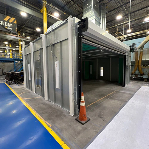
Automotive paint booths are commonly sized around specified vehicle envelopes and workflows, with clearances that vary by model and intended use. When your shop coats heavy structural weldments, electrical control enclosures, large agricultural components, or mixed production runs, that standardized envelope quickly breaks down.
Selecting the right booth is not a matter of simply buying something "bigger and heavier." Pre-engineered, standard-envelope booths can be a practical, economical option where their documented envelope and capabilities fit the production line. However, recognizing when product geometry, material handling, or coating processes require dedicated industrial paint booths saves facilities from expensive retrofit work, compromised finish quality, and dangerous operational bottlenecks.
The Part's Journey: Loading, Spraying, and Handling Geometry
A booth envelope must accommodate the entire operational cycle of the part, not merely its static dimensions. A part that clears the entrance doors can still choke your production line if operators cannot reach all surfaces or if the loading method interferes with airflow.
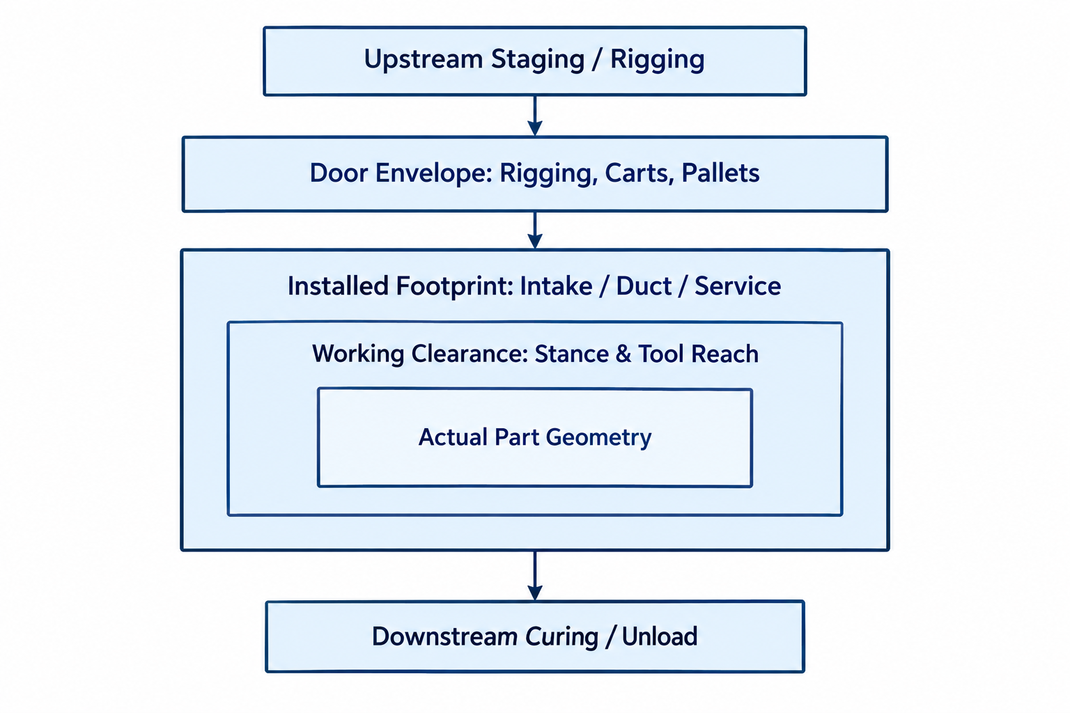
Diagram description
- Upstream Staging / Rigging
- Door Envelope: Rigging, Carts, Pallets
- Working Clearance: Stance & Tool Reach
- Actual Part Geometry
- Installed Footprint: Intake / Duct / Service
- Downstream Curing / Unload
- Upstream Staging / Rigging → Door Envelope: Rigging, Carts, Pallets
- Door Envelope: Rigging, Carts, Pallets → Installed Footprint: Intake / Duct / Service
- Installed Footprint: Intake / Duct / Service → Downstream Curing / Unload
- Installed Footprint: Intake / Duct / Service
- Working Clearance: Stance & Tool Reach
- Working Clearance: Stance & Tool Reach
- Actual Part Geometry
1. Moving the Part into the Cabin
Industrial workpieces rarely roll into a booth under their own power. Fabricated subassemblies require material handling interfaces:
- Forklift tines or extended boom attachments
- Heavy-duty steel caster carts
- Overhead monorails or bridge crane slots
- Floor-mounted tracks
Handling equipment changes the entry clearances. A 6-foot-tall electrical cabinet on a 30-inch-high cart has an 8.5-foot loaded height before any additional handling clearance.
If parts enter via an overhead crane, evaluate how the roof and access arrangement accommodate the actual crane or handling path; a modified enclosure or different loading method may be needed.
2. Physical Reach and Working Space
Once inside, the boundary between the part and the interior booth walls governs labor efficiency. Sprayers must maintain an optimal gun-to-target distance specified for the application equipment and coating system while holding the applicator perpendicular to complex profiles.
If a wide weldment leaves only two feet of clearance on either side, operators may lack the access needed for suitable spraying, hose management, or inspection.
Conversely, an oversized interior may increase required air volume and conditioning costs without improving useful working access.
The goal is functional access: providing adequate room for the operator's stance, gun stroke, and personal protective gear without over-sizing the cabin volume.
3. Installed Footprint vs. Working Dimensions
Shop floors are finite. When laying out equipment, distinguish the clear interior working dimensions from the exterior footprint.
An industrial cabin with a 14-foot clear inside width can require additional floor space beyond that working width once you account for:
- Structural stiffeners and external column supports
- Side-wall exhaust plenum chambers
- Control panels, drive motors, and filter access doors
- Clearances required around mechanical service points
Before finalizing booth positioning, coordinate wall clearances with building columns, overhead joists, and cross-traffic lanes.
Airflow Dynamics and Thermal Processing
Airflow design must reflect the loaded conditions of the booth rather than its empty-shell rating. What passes through the booth—and how it behaves when striking complex profiles—determines whether the ventilation system protects the finish and the operator.
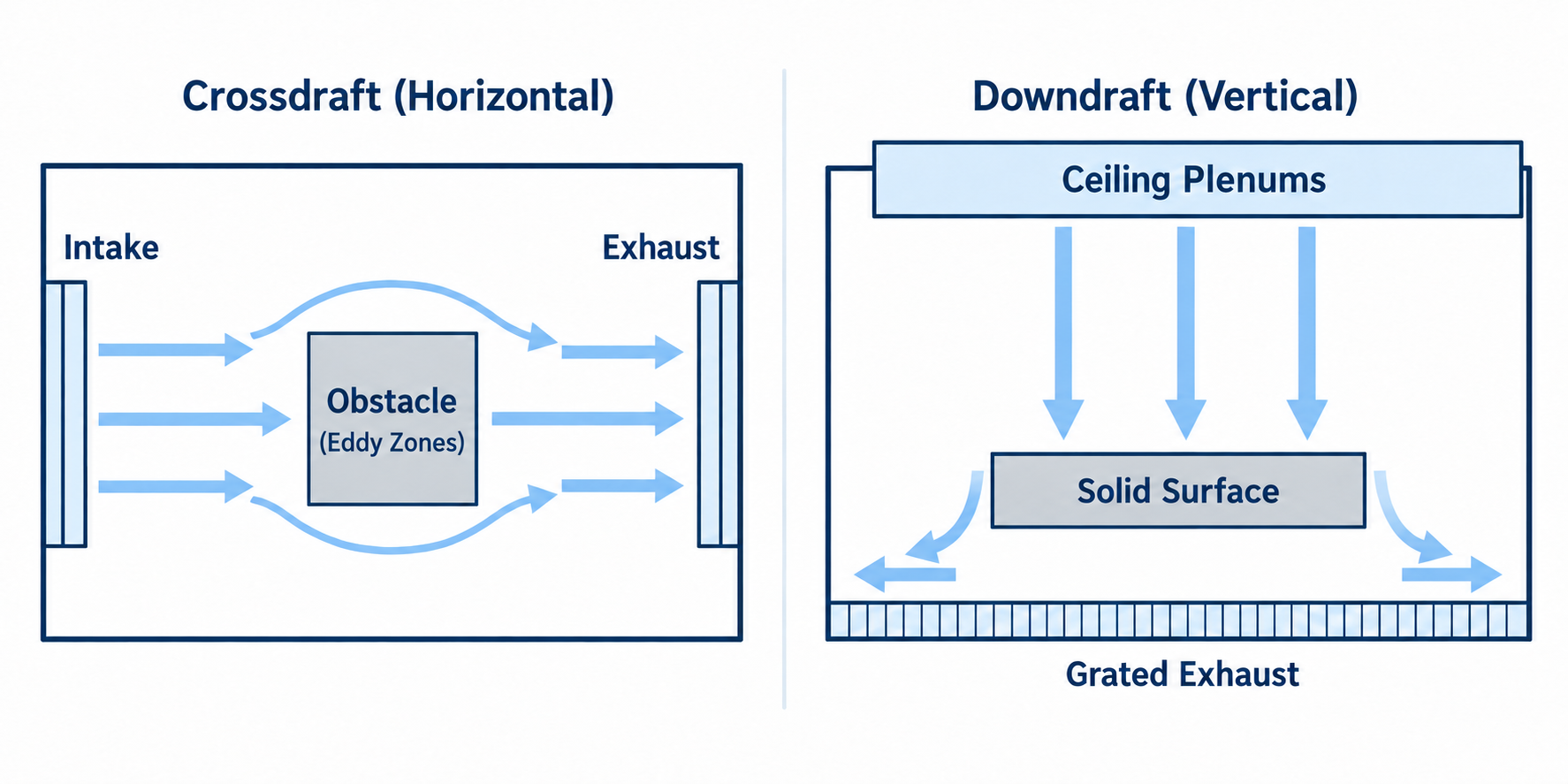
Diagram description
- Crossdraft (Horizontal)
- Downdraft (Vertical)
- Intake
- Exhaust
- Obstacle
- (Eddy Zones)
- Ceiling Plenums
- Solid Surface
- Grated Exhaust
- Intake → Exhaust; horizontal airflow past Obstacle
- Ceiling Plenums → Solid Surface; downward airflow deflects around Solid Surface
- Solid Surface → Grated Exhaust; airflow outside Solid Surface deflects laterally toward Grated Exhaust
- Crossdraft (Horizontal)
- Intake
- Exhaust
- Obstacle
- (Eddy Zones)
- Downdraft (Vertical)
- Ceiling Plenums
- Solid Surface
- Grated Exhaust
- Obstacle
- (Eddy Zones)
Coating Properties, Application Methods, and Curing Modes
Industrial finishes range from fast-drying waterborne primers to slow-curing two-part epoxies and high-solids polyurethanes. Application methods vary equally, from conventional air-spray and HVLP to high-pressure airless and electrostatic systems.
Each combination introduces distinct transfer efficiencies and solvent evaporation curves.
Never assume a booth setup is compatible with a coating without consulting the coating manufacturer’s technical data sheet (TDS). Review the product’s documented requirements, as applicable, for:
- Specified flash-off times
- Maximum booth temperatures during forced-cure cycles
- Specific humidity and airflow velocity ranges required to prevent solvent pop, sagging, or blushing
Forced drying adds mechanical complexity. If your operation requires rapid cycling from spray application to an elevated bake mode, ask the equipment designer about:
- Heating controls suited to the selected equipment
- Any insulation and surface-temperature safeguards needed for the operating mode
- Any permitted recirculation and required purge or transition safeguards
Air Movement Around Irregular Workpieces
Airflow distribution depends on the design and loaded condition. Bulky machinery enclosures, open truss frames, and solid plates can alter local patterns compared with the empty cabin.
Solid, bulky objects create wake effects and low-pressure eddy zones on their downstream faces. Local recirculation can retain or redeposit overspray and affect exposure; evaluate the actual geometry, task, and airflow rather than inferring performance from booth volume alone.
- Air Flow Pattern → Solid Workpiece → Possible Recirculation / Eddy Zone
- Overspray may be retained or redeposited.
- Exposure may be affected.
Airflow patterns must suit the work:
- Horizontal Crossdraft: Air enters the front doors and moves horizontally toward the back exhaust bank. Cost-effective and simple, but upstream parts can push overspray directly over downstream parts.
- Side-Downdraft: Air enters through ceiling plenums and exits through filtered lower sidewall plenums. Eliminates concrete pit excavation, but wide or low-slung parts can deflect air away from the lower center of the part.
- Full Downdraft: Air enters through the ceiling supply and is drawn toward floor exhaust. A pit or raised-floor arrangement may be used; the actual design, loaded airflow, and access requirements determine fit and performance.
Compliance requires grounding your airflow selection in established standards. OSHA's spray-finishing standard (29 CFR 1910.107) and OSHA's spray-finishing ventilation requirements (29 CFR 1910.94(c)) include scoped ventilation and vapor-dilution provisions; evaluate the applicable process requirements rather than one universal airflow value.
An established manufacturer's reference, such as Rohner's safety and compliance manual, underscores that field performance depends on maintaining filter hygiene, static pressure baselines, and loading configurations according to the unit's intended design. Calling a booth "industrial" does not exempt it from continuous compliance.
Evaluating the Work: Standard Envelope vs. Industrial Requirements
The table below breaks down the technical differences between standard, vehicle-centric equipment and custom industrial configurations. Use this to determine what information to pull together before requesting equipment pricing.
| Operational Factor | Standard / Pre-Engineered Fit | Industrial / Custom Need | Technical Information to Provide |
|---|---|---|---|
| Product Dimensions & Mix | Predictable, uniform envelopes that fit the documented model envelope. | High-mix parts, extreme heights, structural trusses, open weldments, or asymmetric machinery frames. | Max length, width, height, and dry weight of the largest three parts; profile schematics of typical mix. |
| Operator Access & Ergonomics | Ground-level access; full 360-degree walking path without elevation equipment or custom staging. | Evaluate elevated access, suitable work platforms, and applicable fall protection for the actual tasks. | Target spray heights, operator reach envelopes, safety anchor points, and clearance for lift platforms. |
| Material Handling & Loading | Roll-in components, floor jacks, small carts, or manually rolled caster racks across smooth thresholds. | Monorail conveyors, crane slots, tow-chains, heavy pallet jacks, or direct forklift loading through open-top roofs. | Handling equipment type, wheel/axle loads, track centerlines, crane hook heights, and slot-sealing needs. |
| Process Demands & Cycles | Ambient flash-off, standard batch air-dry, or basic direct-fired auto-refinish thermal cycles. | Two-component fast-cure chemistries, high-heat continuous cures, multi-stage purge, or automated gun integration. | Coating TDS (flash times, cure temps, VOC levels), transfer efficiency rates, daily batch count, and shift schedule. |
Production Interfaces and Project Coordination
A booth’s performance depends partly on the upstream, downstream, and building interfaces supporting it. A failure to plan these tie-ins stalls commissioning and blows project budgets.
- Natural Gas / Propane → Air Makeup Unit → Paint Booth Enclosure
- Main Electric Service → Control Panel → Paint Booth Enclosure
- Plant Air Compressor → Air Drops / Regulator → Paint Booth Enclosure
- Paint Booth Enclosure → Exhaust Ductwork → Roof Penetration / Stack Clearances
Upstream Staging and Downstream Transfer
Bottlenecks typically occur outside the booth doors. If a welded frame takes 45 minutes to spray but requires 30 minutes to rig, stage, and align onto its handling cart, that handling adds 30 minutes before each spray cycle unless it can be staged independently.
- Build staging space immediately ahead of the intake doors.
- Design a clean, designated flash-off footprint downline so finished items dry without gathering shop dust or holding up the next batch.
Utilities and Air Makeup Balancing
Industrial finishing demands clean, dry plant air and high-capacity electrical and fuel connections.
- Compressed Air: Assess process-air capacity and quality for pneumatic tools and pumps. Breathing-air systems require separate evaluation against applicable respiratory air-quality provisions; do not assume an ordinary shop compressor supply is suitable.
- Electrical Supply: Main supply panels must feed the booth lighting, exhaust fans, safety interlocks, and burner blowers. Have the responsible electrical designer determine actual classifications, boundaries, and suitable equipment for the process.
- Air Makeup Units (AMU): Exhausted air needs adequate replacement air to maintain the designed booth and building air balance. Direct-fired gas makeup units supply heated, filtered replacement air to maintain neutral building pressure. Inadequate replacement air can create negative building pressure, backdraft combustion equipment, and draw uncontrolled dust or outside air into the work area.
Exhaust Routing and Structural Clearances
Plan an exhaust route that meets applicable discharge, construction, and cleaning-access provisions; horizontal ducting is not categorically prohibited, but deposits and access must be addressed.
- Plan the roof penetration early: verify structural roof joist positions, wind load requirements for exterior stacks, and exhaust termination points.
- Building codes require exhaust stacks to terminate well away from building air intakes, doors, and operable windows to prevent re-entraining VOCs into the facility.
Moving from Evaluation to Implementation
To select the right equipment, start by defining the physical and chemical realities of your parts: their shapes, how they move through the plant, and how they cure. Pre-engineered models may offer shorter lead times and lower acquisition costs where the specified model suits the process; confirm the actual quote and capabilities.
When your parts challenge that box, evaluate whether a different pre-engineered model or custom configuration addresses the handling, access, and airflow requirements.
To streamline this evaluation:
- Audit your process parameters: Assemble your parts mix, material handling paths, and technical data sheets using our paint booth design checklist.
- Review local code and facility requirements: Work with local authorities to address zoning, fire suppression interlocks, stack exhaust heights, and paint booth permit requirements.
- Engage engineering for structural fit: When you are ready to review floor layouts, airflow profiles, or custom handling slots, request a paint booth quote to work with our engineering team on tailoring a pre-engineered standard or custom configuration to your production floor.