Selecting access equipment for finishing operations requires separating how a platform moves through space from how its chassis travels across the shop floor. Conflating these two factors leads facilities to install lifts that meet basic ceiling heights but collide with part profiles, obstruct booth airflow, or create compliance hazards in classified spray zones.
Finishing work introduces process constraints that general construction lifts never face. Overspray accumulation, volatile solvent vapors, abrasive blast media, and tight booth enclosures demand a deliberate match between platform geometry, utility integration, and environmental ratings.
Finishing Access Lift Types: Geometry Versus Travel Mechanics
Lift taxonomy rests on a two-axis framework: reach geometry on one axis and chassis travel or mounting on the other. Evaluating equipment along both axes prevents baseline sizing errors.
- REACH GEOMETRY (How the platform moves through space)
- Scissor: Pure vertical lift on folding linkages
- Articulating / Telescopic Boom: Linear outreach and over-obstacle knuckles
- Vertical Mast: Compact vertical ascent on a rigid column
- Three-Axis Rail / Wall: Coordinated vertical, horizontal, and depth motion
- TRAVEL & MOUNTING (How the system moves through the facility)
- Self-Propelled / Driveable: Motorized chassis operated from platform
- Push-Around: Manually rolled on casters; stationary during use
- Floor-Track Guided: Follows embedded floor rails along the part line
- Wall-Mounted Rail: Suspended on booth walls, clear of floor grates/airflow
Mobile Boom, Scissor, and Vertical Mast Lifts
Mobile lifts utilize independent, wheeled chassis that position operators along structural assemblies or transport them between prep bays.
Scissor lifts rely on linked pantograph mechanisms to raise platforms straight up. They offer large deck platforms and robust carrying capacities, allowing multiple operators to work simultaneously with pressure pots, spray guns, and fluid lines. However, scissors offer no horizontal outreach beyond manual deck extensions. They require direct, unobstructed floor placement beneath the target surface.
Boom lifts provide horizontal outreach and vertical range. Telescopic booms push straight out along a linear axis, offering stiff extensions over wide flatbeds or structural beams. Articulating booms incorporate intermediate pivot joints—knuckles—that allow the operator to reach up, over, and behind complex weldments, vehicle cabs, or wing profiles.
Comparing boom and scissor reach highlights this trade-off: a boom solves reach-over challenges but demands broad sweeping clearance for its counterweight and knuckle radius, whereas a scissor lift primarily provides vertical access; its chassis and deck-extension clearances still need checking.
Vertical mast lifts use an upright, telescoping column to raise a single operator. Many models offer compact floor footprints. Propulsion is a separate selection factor: facilities choose between driveable and push-around vertical lifts.
A push-around mast lift must be manually pushed into position and set up according to its operating manual before raising the platform; it is not self-propelled. Confusing push-around units with driveable equipment will disrupt process timing if an operator must descend, exit the platform, and manually reposition the machine to coat successive sections of a continuous workpiece.
Purpose-Built Finishing Access Systems
Standard mobile access equipment often introduces severe geometric and operational friction inside a production spray enclosure. Floor-mounted tires crush paper masking, pinch fluid hoses, track wet overspray throughout the booth, and block crossdraft floor exhaust trenches.
Purpose-built paint booth personnel lifts solve these spatial conflicts by mounting directly to the booth side walls or traveling on low-profile floor rails integrated into the booth structure.
These dedicated finishing systems eliminate bulky counterweights and tires from the working floor. By integrating fluid lines, atomizing air drops, and respiratory air feeds directly through articulated mast umbilicals, purpose-built systems keep the floor clear. They also keep the operator in continuous ergonomic alignment with long parts like railcars, aerospace fuselages, and heavy commercial trailers.
Matching Platform Reach and Motion to the Workpiece
Nominal category height ratings are inadequate metrics for finishing layout. The coating process and applicator instructions determine the required spray distance and orientation. Evaluating access equipment requires working-envelope drawings that map the operator's actual reach against the workpiece profile.
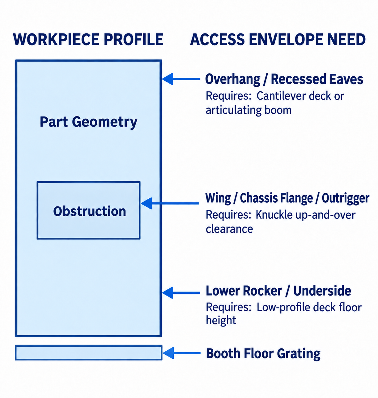
Diagram description
- WORKPIECE PROFILE
- ACCESS ENVELOPE NEED
- Part Geometry
- Obstruction
- Overhang / Recessed Eaves
- Requires: Cantilever deck or articulating boom
- Wing / Chassis Flange / Outrigger
- Requires: Knuckle up-and-over clearance
- Lower Rocker / Underside
- Requires: Low-profile deck floor height
- Booth Floor Grating
- Part Geometry
- Obstruction
- Left title WORKPIECE PROFILE; tall rectangular enclosure with Part Geometry near upper interior and a smaller inner rectangular Obstruction at middle.
- Horizontal Booth Floor Grating below outer enclosure.
- Right title ACCESS ENVELOPE NEED.
- Three LEFT-pointing callout arrows target upper outer wall, inner obstruction, lower outer wall respectively.
- Upper callout Overhang / Recessed Eaves with Requires: Cantilever deck or articulating boom.
- Middle Wing / Chassis Flange / Outrigger with Requires: Knuckle up-and-over clearance.
- Lower Lower Rocker / Underside with Requires: Low-profile deck floor height.
- Fourth left-pointing callout Booth Floor Grating targets floor line.
- Overhang / Recessed Eaves
- upper outer wall
- left
- Requires: Cantilever deck or articulating boom
- Wing / Chassis Flange / Outrigger
- Obstruction
- Requires: Knuckle up-and-over clearance
- Lower Rocker / Underside
- lower outer wall
- Requires: Low-profile deck floor height
- Booth Floor Grating
- floor line below workpiece
Platform sizing must account for dynamic payloads rather than bare operator weight. Total load calculations must include:
- The operator and personal protective gear.
- Supplied-air respirators and hose lines.
- Spray guns, heaters, and fluid regulators.
- Suspended fluid and air umbilicals spanning from the wall or mast.
- Staged touch-up materials or pressure vessels.
Part contours dictate whether vertical travel alone is sufficient. When coating box vans or flat structural panels, vertical travel paired with linear travel covers the surface. When workpieces feature stepped profiles, engine cowlings, or railcar roof curves, operators need horizontal articulation to reach over obstacles without overextending their bodies outside the platform rails.
In high-throughput industrial settings, dedicated three-axis positioning enables an operator to move along the booth length (X-axis), adjust vertical height (Z-axis), and extend outward toward the part face (Y-axis). This three-dimensional control can reduce repeated lowering and repositioning when its working envelope fits the part.
Hose and umbilical management is equally vital. Scissor arms create severe pinch points that can sever fluid lines or air hoses. Booms sweep through arcs that risk snagging supply whips on part corners. Dedicated finishing access equipment routes utilities through sealed, articulated internal tracks or overhead festoons, keeping hoses isolated from moving linkages and clear of the coating zone.
Booth Infrastructure, Hazardous Locations, and Environmental Limits
Installing an access lift inside a finishing facility alters booth aerodynamics, structural loading, and hazardous area classification. Equipment must be engineered for the specific chemical and physical environment of the enclosure.
BOOTH INTEGRATION CHECKLIST
- ☐ Floor Capacity: Point-loads verified against grating and pit limits
- ☐ Airflow Clearance: Equipment profile does not choke laminar cross/down draft
- ☐ Atmosphere: Drive/controls approved for the assessed work zone
- ☐ Utility Supply: CFM, pressure, and voltage match booth connections
- ☐ Thermal Limits: Seals and hydraulics rated for bake-cycle temperatures
Floor Loading and Enclosure Clearances
Industrial booths frequently employ subterranean exhaust pits covered with bar grating. Mobile scissor and boom lifts exert extreme, concentrated wheel point-loads over small contact patches. Standard grating can deform or fail under the combined weight of a solid steel counterweight and ballast.
Before placing mobile units on grating, verify wheel loads against the structural structural limits of the pit support steel. Wall-mounted lifts bypass the floor entirely, but they transmit dynamic horizontal and vertical loads into the booth structural frame. Wall columns and building anchor points must be engineered to support these cantilevered loads.
Enclosure volume must accommodate both the machine envelope and designed airflow patterns. In large equipment paint booths, introducing a wide scissor base or heavy boom chassis between the wall and the part can disrupt designed laminar airflow. Choking the clearance creates turbulent eddies, causing overspray to swirl back onto freshly coated panels or drop onto the operator's visor.
Hazardous Location Compatibility and Harsh Environments
Finishing environments present volatile atmospheres, airborne particulates, and aggressive solvents. General construction lifts may contain ignition sources and lack approval for the assessed spray environment.
Complying with ignition-source requirements in spray areas, as outlined in OSHA 1910.107 and NFPA standards, dictates which drive and control systems are permissible. The responsible designer must assess the work zone and verify the equipment approval against the applicable hazardous-location requirements.
Pneumatic (air-driven) platforms are widely used in finishing booths because air motors do not generate electrical arcs. However, pneumatic operation alone does not constitute universal compliance.
Grounding, static control, materials, and control-system protection must be reviewed as part of the complete installation; a list of individual components does not establish equipment approval.
Powder coating booths also require assessment of combustible dust and residue accumulation. Ask the lift and booth suppliers how the equipment will be cleaned and maintained without trapping powder in linkage pockets.
Thermal curing conditions must also be factored in. If a lift remains inside a combination spray-and-cure booth during heated bake cycles—at the specified cycle temperatures—the supplier must verify the temperature ratings of hydraulic hoses, cylinder packings, air line seals, and electronic sensors.
Preparing the Lift-Selection Project Brief
Selecting access equipment requires presenting equipment suppliers with an operational brief based on actual plant data. Relying on rough estimates leads to costly field modifications, non-compliant installations, and operator bottlenecks.
PROJECT DATA SHEET: FINISHING ACCESS
- Workpiece Envelope: L: _____ ft | W: _____ ft | H: _____ ft
- Maximum Part Weight: _____ lbs
- Profile Complexities: [ ] Undercuts [ ] Recesses [ ] Cantilevers
- Booth Dimensions: L: _____ ft | W: _____ ft | H: _____ ft
- Exhaust Style: [ ] Full Downdraft [ ] Semi-Downdraft [ ] Crossdraft
- Floor Construction: [ ] Solid Slab [ ] Bar Grating [ ] Pit Tracks
- Environmental Rating: Assessed work-zone classification: __________________
- Finishing Chemistry: [ ] Solvent-borne [ ] Waterborne [ ] Powder
- Maximum Bake Temp: _____ °F
- Total Deck Payload: _____ lbs (Operator + Equipment + Wet Lines)
- Utility Feeds Needed: [ ] Compressed Air [ ] Fluid Drops [ ] Breathing
Compile the following baseline parameters before engaging manufacturers:
-
Part Envelope and Working Zones
Gather dimensional part drawings showing maximum height, width, and lowest ground-clearance targets. Identify recessed pockets, overhangs, and compound curves that require articulating reach. Define whether operators coat stationary parts or work along continuously indexing conveyors. -
Booth Structural and Airflow Parameters
Record exact internal cabin dimensions (length, width, clear height below lighting and filter banks). Detail the floor design: slab-on-grade thickness, pit depths, grating bar load profiles, and door swing arcs. Specify booth airflow direction (crossdraft, side downdraft, or full downdraft) and velocity. -
Total Platform Loading and Utility Drops
Calculate the peak payload by totaling operator weights, protective gear, spray tools, and material pots. Document all utilities that must terminate at the platform deck, such as compressed air volume (SCFM at PSI), fluid delivery lines, electrostatic power supplies, and breathing-air lines. -
Atmospheric and Thermal Classifications
Determine the hazardous area classification of the work zone based on coating chemistries, ventilation design, and application methods. Record peak booth operating temperatures, factoring in flash-off cycles, force-dry modes, and high-heat cure operations. -
Facility Training and Maintenance Access
Plan for regular maintenance clearance. Verify that service personnel can inspect fluid levels, mechanical linkages, emergency descent controls, and track seals without disassembling booth walls or compromising cleanroom seals. Establish equipment-specific operator qualification protocols tailored to the unique visibility limits and pinch zones of paint enclosure work.
Once your dimensions, clearances, and operational targets are assembled, contact PaintBooth.com to request an equipment quote based on your specific application brief. Matching validated structural and safety data to purpose-engineered access platforms protects cycle times, finish quality, and regulatory compliance across your finishing line.